Q1 Plans Chapter 14 Page 14-4
- Details
- Category: Quickie Plans
- Published: Monday, 12 May 2008 10:28
- Written by Dan Yager
- Hits: 1970
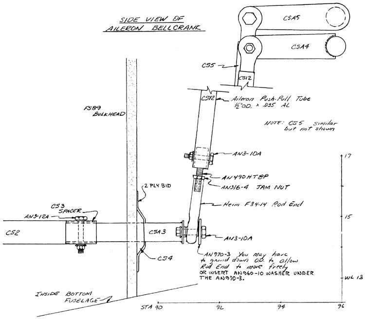
CS2 is a 6’ length ot 3/4” O.D. x .035” wall aluminum tubing. At the cockpit end, a 1” length of CS3 spacer is used to join it to CSA2. At the aft end, another 1” length of CS3 spacer is used to join CS2 to CSA3.
First, however, you must route CS2 through the fuselage and install CS4 bearing. The center of CS4 should be located at WL14.5, and about 3” inboard of the fuselage side. CSA3 must be able to pivot freely without hitting the fuselage side. Also, you will have to route holes in the seatback bulkhead and the FS89 bulkhead to permit CS2 to pass through without interference. To install CS4, it is best to jig CSA2-CS2-CSA3 together and temporarily 5 minute CS4 in place. Then you can remove them and layup 2 BID over CS4 to attach it to the FS89 bulkhead, remembering to keep epoxy out of the bearing hole.
Once CS4 has cured, the rest of the control system can be hooked up as shown. The CS13 elevator pushrod, and the CS5 and CS12 aileron pushrods should not be installed until after the canard and main wing are mounted on the fuselage so that accurate lengths can be measured.
The AN3-12A bolts that go through CS2 deserve some special attention also. Looking at the front view of CSA1, you will notice that it is canted inboard toward the center of the cockpit. Note also that the fuselage side around the stick is carved out to the outside fuselage skin,. These two items are necessary to provide hand and knuckle cleareance for the pilot to get full right aileron. To set this up properly, sit in the cockpit and move the stick around, marking on the fuselage side where you need additional knuckle clearance. Then, simply grind down to the outside skin in that area and layup two BID as a patch. Of course, remember to keep the contouring smooth and to avoid bumps and joggles. The AN3-12A bolt connecting CS2 and CSA2 should be drilled in now. The AN3-12A bolt that connects CSA3 to CS2 should not be drilled in until the rear wing has been mounted and the aileron system is hooked up. In this fashion, you will be able to orient CSA2 so that you can obtain full right aileron travel at the stick.
The stick grip is carved from balsa wood and mounted to CSA1 with epoxy.

CONTINUED ON NEXT PAGE


