Login Form

Q1 Plans Chapter 13 Page 13-3

MOUNTING THE CANARD TO THE FUSELAGE

The canard is permanently attached to the fuselage with 2” BID tapes on both the inside and the outside of the fuselage.

Begin by leveling the fuselage both longitudinally and laterally. The fuselage should be high enough off the ground that the canard can be slipped under it and up into position without noving the fuselage.

The procedure for fitting the canard to the fuselage is one of fitting, then trimming, then fitting again until the canard smoothly mates to the fuselage.

Some important points to remember as you are doing this work are:

  1. When the fuselage sides were made, the BL10 canard template was used to approximate the cutout. This cutout will have to be trimmed to fit the real canard.
  2. The level board on the canard must be level when the canard is joined to the fuselage. Recheck fuselage level also.
  3. Avoid having to use lots of dry micro to fill voids during the final mating process by being careful in the trimming process.
  4. Check to make sure that the canard centerline is on the fuselage centerline.
  5. Check the skew of the canard by measuring the distance from the axle to STA172 (where the tailspring meets the fuselage) on each side. They should be equal.

When everything is ready, mix up dry micro and apply it liberally to both the canard and to the fuselage wherever the two will mate. Gently lower the fuselage into position on top of the canard. Make sure that you obtain good squeeze out everywhere and then remove the excess.

Now, once again check the level of the canard and fuselage, as well as the skew of the canard. When you are sure that everything is absolutely perfectly lined up, leave the aircraft alone for about a day in order for the micro to cure.

Then, you can begin applying the BID tapes that provide the real strength. Note that two tapes are used everywhere both inside and out.
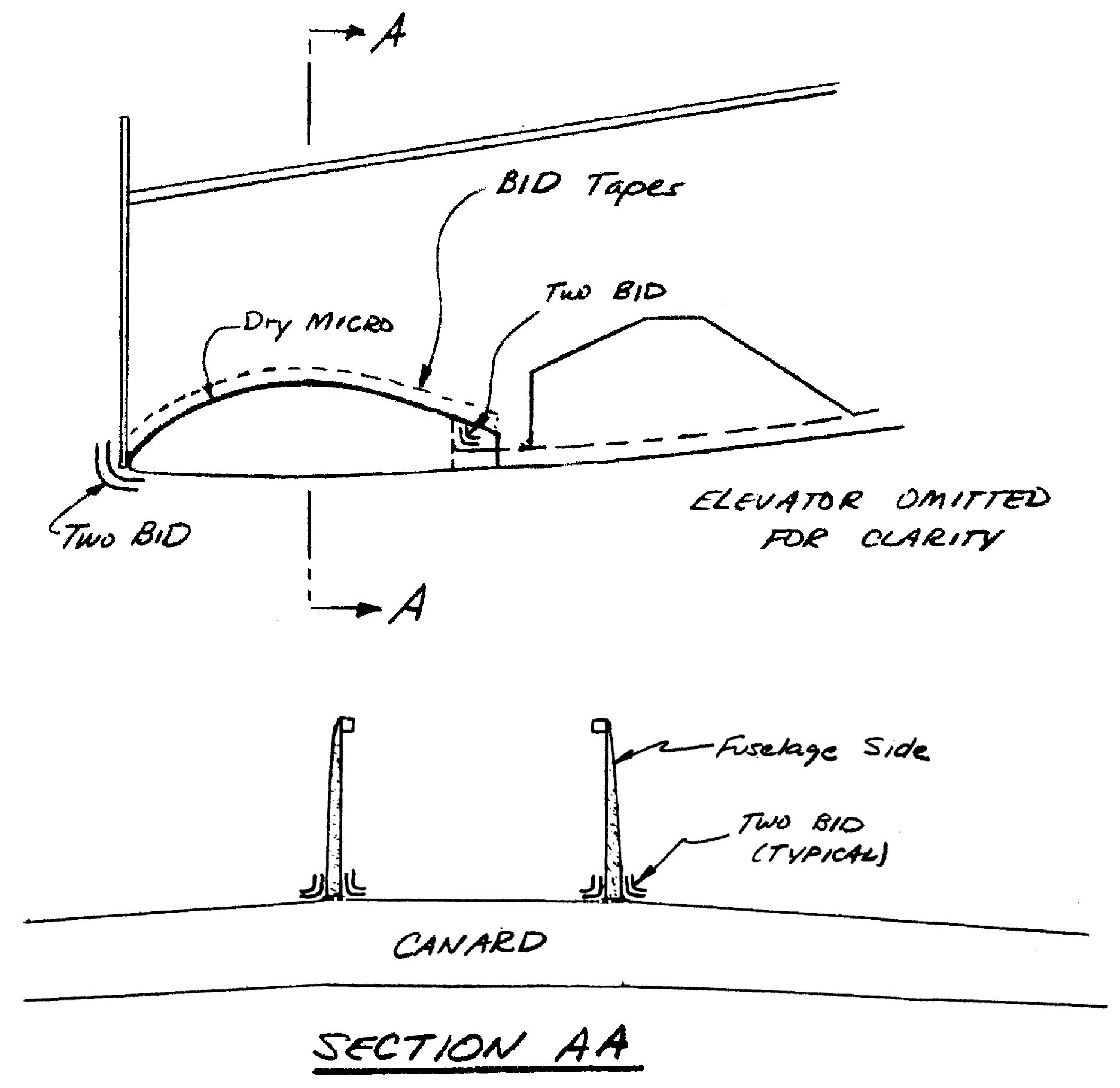

Quickie Install Canard

Q1 Plans Chapter 14 Page 14-1

SIDE CONSOLE INSTALLATION

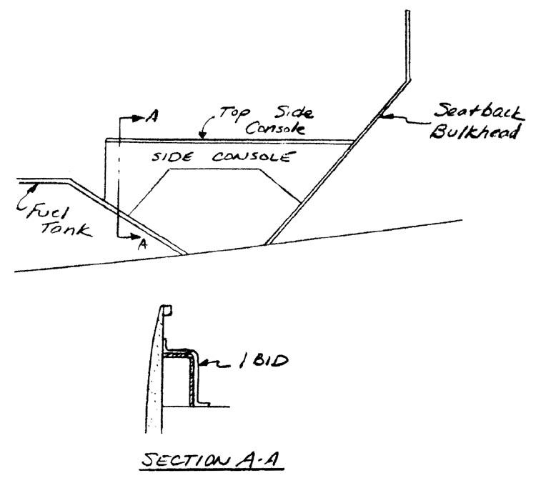
The side consoles can now be installed. Use one BID over the bare orange foam side, overlapping onto the fuselage, fuel tank, and seatback bulkhead. Some trimming of the sides may be necessary because of differences in your locations of the fuel tank, etc. Also, the top side console rests on top of the side console.

After installation, therefore, you will have one ply of BID on each face of the consoles.

Quickie Side Console Installation

TRIM SYSTEM

Roll trim and rudder trim are both ground ajustments. The pitch trim can be altered in flight, even though for most flying, you will probably find that you don’t retrim very often.

Roll trim is adjusted by changing the length of the rod end combination that joins CSA6 and CSA7. This must be done on the ground, of course.

Rudder trim should be accomplished by placing a small tab on the rudder and bending it to make the rudder trim at the desired angle. Remember that bending the tab right will make the nose go left. The rudder trim should only be installed if flight test proves it necessary.

Pitch trim is actuated by an arm on CSA8 with two springs attached to it. The tension in the aft spring can be varied by the position of the trim handle, which is a sawed-off hacksaw blade. Changing the tension in the aft spring will cause the CSA8 trim arm to rotate to a new position, which means that the elevators have rotated to a new position. Look at the sketch and understand the last few sentences.

The details show you how to hook up the system. There are several things that should be noted. The springs are fastened to the AN100-3 thimbes and the hacksaw blade by looping safety wire around the combination two times. Of course, the last loop of the spring should be closed so that the safety wire cannot slip out. With the elevator at neutral position, the CSA8 trim arm should be approximately vertical. The lengths given for the springs are the unstreched lengths and are approximate; once the trim system is installed you may have to stretch, or shorten one or both springs to get the proper trim travel. Without touching the stick, the trim system should be able to trim the elevator within a plus or minus 10 deg. range from neutral. If necessary, favor the down elevator condition slightly.

For the trim arm, cut a hacksaw blade from the local hardware store to the correct length. Deepen the notches with a file so that they are at least 1/8” deep. This will mean that you will end up with half as many teeth in order to get the proper depth.

Another piece of hacksaw blade is attached with 5-Min to an orange foam bulkhead, which is mounted at the fwd. end of the fuel tank using 2-BID on each side. A slot in the foam allows the hacksaw blade to rest on the blade attached to the orange foam. To trim the aircraft in pitch, you just lift up and move the hacksaw blade until a different notch rests in the blade attached to the orange foam. Macrame beads from the variety store are attached to the hacksaw blade as a handle. Make sure that throughout the full travel of the trim system, no interference exists with the side console or fuel filler tube.

SEE NEXT PAGE FOR SKETCHES AND DETAILS: