- Details
-
Category: Quickie Plans
-
Published: Monday, 12 May 2008 12:27
-
Written by Jun Su
-
Hits: 4828
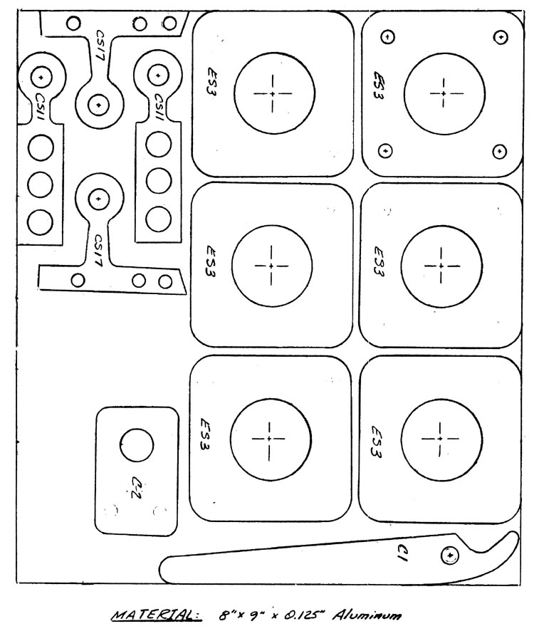
MAKING THE .125" ALUMINUM PARTS
Included in this section is a full
size layout to allow you to make all of
the .125" thick aluminum parts in the
aircraft. All parts are numbered, and
these numbers should be written on the
pieces as soon as they have been made
to avoid loosing track of them.
ES3 are the engine mount plates.
As you can see, there are three pairs
of two. The four holes on the first
layout are .189" diameter. The first
one should be used to drill the holes
in the next two, and then these three
should be labled left, right, and center,
and then used to drill in the remaining
one of each pair. Don't allow the pairs
to become intermingled. The hole in
the center of ES3 is 1.25" in diameter.
It may be cut with a hole saw or fly
cutter. As before, cut this hole in
pairs.
The holes in the eyes of CS11 (2)
and CS17 (2) are 5/16" diameter. The
rest of the holes in these pieces are
to help the bonding and need be only
the approximate diameter shown.
The hole shown in C1 is 5/16"
diameter, and a CSM4 bushing is pressed
into the hole after it is drilled. The
hole in C2 is 1/2" diameter.
The squares are used for nutplate
mounting.
CSM4 bushings should also be
pressed into the "eyes" of the two
CS17's and the two CS11's.