- Details
-
Category: Quickie Plans
-
Published: Monday, 12 May 2008 10:28
-
Written by Dan Yager
-
Hits: 2331
FABRICATING THE CARB SCOOP
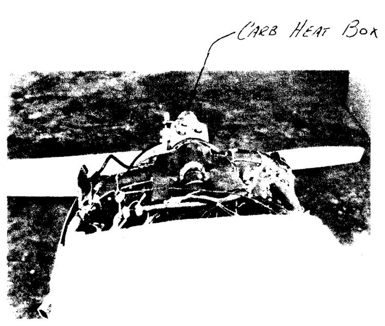
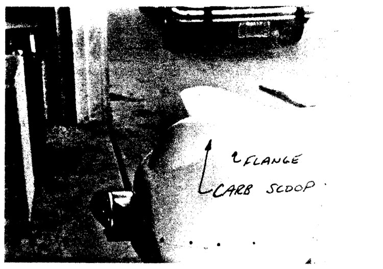
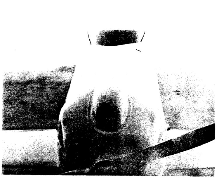
In order to provide adequate clearance for the Carb Heat Box on top of the engine, you will have to fabricate a simple bump, or scoop, and pop rivet it to the top of the cowling.
Begin by rounding up the scraps of blue foam that you have remaining. With the cowling and carb heat box in place, place the foam on top of the cowling and carve it to a pleasing shape that will cover the carb heat box and fit flush with the top of the cowling.
When you are satisfied with the shape, remove the foam block from the aircraft and set it on a piece of clear plastic wrap. Next, lay up 3 BID over the foam, allowing the fiberglass to drape onto the clear plastic wrap to form a flange at least 0.6" wide. Permit the layup to cure overnight.
Now comes the neat part. Pour gasoline on the blue foam to dissolve it, leaving only the fiberglass layup. Now you can clean up the scoop, and rivet it to the cowling.
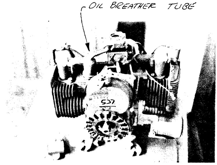
OIL BREATHER TUBE
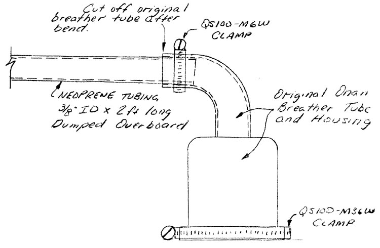
The oil breather tube is vented overboard at the bottom of the cowling. The original Onan breather tube and housing are extended with neoprene tubing.
