Q2 Plans Chapter 8 Page 8-03
- Details
- Category: Q-2/Q-200 Plans
- Published: Tuesday, 23 May 2006 09:05
- Written by Quickie Aircraft Corporation
- Hits: 5313
|
canted portion to be moved aft, which increases cockpit room. Moving the break point up moves the canted portion of the Seatback Bulkhead forward_ making the cockpit more comfortable for shorter people. The nominal FS64 shown on the sketch as the intersection
of the forward edge of the seatback bulkhead and the fuselage bottom is optimum for people up to 616".
The forward face of the Seatback Bulkhead must be at FS78.
.....Once the Seatback Bulkhead is trimmed for position, you may trim the FS94 bulkhead. For many reasons_ this bulkhead does not go at FS94, and is the only exception to the relationship between fuselage stations and locations. The FS94 bulkhead should be located so that the forward face of the FS94 bulkhead is at FS95. This is to allow proper clearances and fitting for the main wing upon its installation later. .....All bulkheads are mounted vertically (use a level) except for the canted part of the Seatback Bulkhead. When you feel comfortable with the fit, (no, we are not talking about all the cockpit time youlve been giving yourself!) then bond the bulkheads to the lower fuselage shells. The FS120 and FS175 bulkheads receive 1 BID tape front and back around the joint with good micro squeeze out, the seatback bulkhead and FS94 bulkhead receive 2 BID tapes front and back, and BID tapes to join the canted and upright portions of the Seatback Bulkhead. (Be sure to bevel the intersect ion). The firewall is mounted with 3 BID tapes outside, wrapping around the corner (which means you will have to radius the edge) and 2 BID tapes on the inside. Gentlemen and Ladies, each BID tape must lap onto the fuselage and bulkhead a minimum of 1 inch for proper structu_al joining. Use the level to check for the vertical orientation, and check the squareness of each bulkhead with respect to BLOO. .....Do not install the instrument panel or fuel tank at this time. MOUNTING THE CANOPY
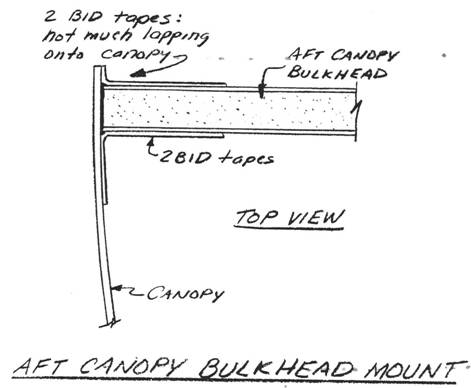
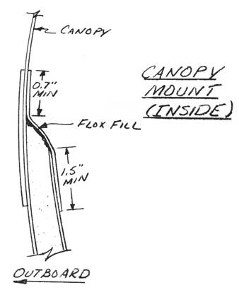
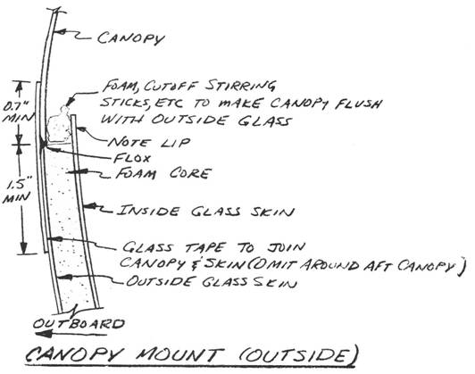
..... Next on the agenda is to permanently attach the canopy to the upper forward fuselage, in preparation for cutting out the canopy frame. The procedures used are basically to final trim the cutout and canopy for fit, then to glass the outside canopy to the outside fuselage, and finally to fit the aft canopy bulkhead and glass the inside of the canopy to the inside of the fuselage. .....Note that the sketch shows a lip on the inside fuselage glass. This lip is to assist in jigging the canopy in position for those outside fuselage tapes. Since the canopy is much thinner than the fuselage core, stirring sticks, foam, etc. will need to be used to provide a firm surface to laminate the outside tapes against. .....The canopy is joined to the outside fuselage with 2 BID tapes, overlapping the fuselage a minimum of 1.5 . inches_ and the canopy a minimum of 0.711. Liberal Flox is used to fill any voids prior to glassing; peel ply the lamination and allow it to cure 24 hours:  ..... Next, the canopy mounted to the fuselage is turned over and the aft canopy bulkhead fitted into position. The aft face should be located a maximum of 1/8" forward of the forward face of the Seatback Bulkhead with a few dabs of 5-MIN. It is permanently mounted with' flox and 2 BID tapes on either side, lapping onto the bulk head and fuselage a minimum of 1.5 inches, and lapping onto the canopy a minimum of 0.7 inches.  ..... Also, sand down the lip in the inside fuselage skin lamination and contour the inside fuselage skin smoothly into the canopy. Then laminate 2 BID (with liberal Flox to fill the voids prior to glassing) with 0.7 inch minimum lapping onto the canopy and a minimum of 1.5 inches lapping on the existing fuse lage inside skin. .....Permit the laminations to cure for 24 hours.  |
||||
|
||||
PAGE 8-3 |
||||


