Q1 Plans Chapter 17 Page 17-2
- Details
- Category: Quickie Plans
- Published: Sunday, 08 June 2008 01:00
- Written by Jun Su
- Hits: 2343
FORWARD FACE OF THE FIREWALL
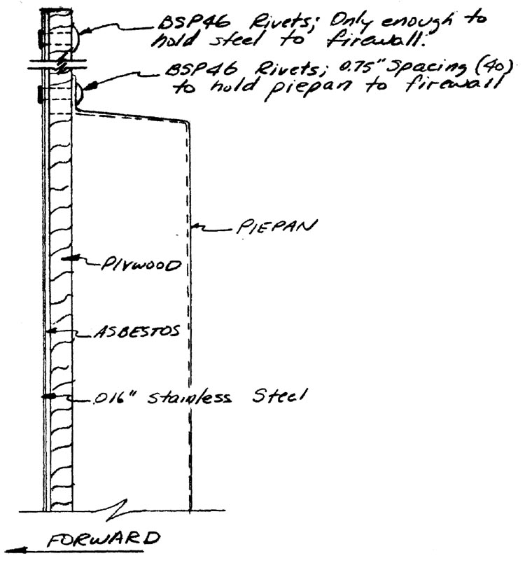
On the forward face of the firewall, it will be necessary to place asbestos and stainless steel(.016” thick) as well as to mount the steel firewall extension (referred to as the “piepan”).
Begin by measuring and cutting the .016” stainless steel to the shape of the firewall. It is probably easiest to use the firewall on the airplane for a template.
Next, do the same thing with the asbestos material.
When you originally cut the plywood firewall out, you drilled a pilot hole for the centerline of the crankshaft. Working from the cockpit side with a pen, carefully mark this point on the steel.
Round up the steel piepan and use it to cut out both the plywood firewall and the stainless steel piece. The piepan should be a loose fit in the plywood and the stainless steel. However, since you will be riveting the piepan to the firewall, be careful not to make too big of a hole or you will have insufficient edge distance for the rivets.
The drawing shows what the combination looks like. Use .75” spacing on the rivets all the way around on the piepan and enough rivets to join the stainless steel-asbestos-plywood together. It is easier to do the piepan last. Be sure to rivet the stainless in the corners so that it won’t pull up.
Finally, open up all of the engine mounting holes in the firewall that were covered up when the asbestos and steel was put on the forward face. Drill thru from the back side of the firewall.

INSTALLING THE ENGINE MOUNTS
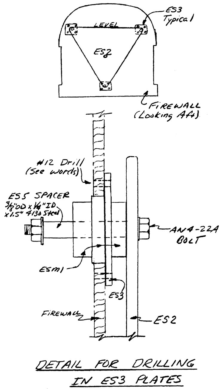
When you originally cut out the firewall, you drilled a 1/4” pilot hole that represented the centerline of the engine crankshaft. You also previously drilled a 1/4” pilot hole through the engine mounting plate (ES2) center, as well as 1/4” holes in ES2 to represent the locations of the three engine mounts.
Begin by leveling the fuselage across the canopy rails so that the fuselage is level in roll. Mount ES2 on the firewall, using a 1/4” bolt through the centerline hole to hold it in position. Level ES2 and check the level on the fuselage again. When satisfied, drill a 1/4” hole through the three engine mount holes through the firewall.
Next, use a flycutter to cut the three mounting holes out to a 1.50” diameter. You may want to experiment with scrap plywood because the diameter is critical. An alternate method would be to use a hole saw.
Make up three partial engine mounts as shown, and bolt them to the ES2 plate, using as many washers as necessary.
Place the ES2 plate with mounts up against the firewall, pushing the mounts into the holes. Orient the ES3 plates as shown and drill all the holes that you can reach with a number 12 drill by drilling from the front side through ES3 through the firewall. You will be able to drill 2 of the holes in each ES3; the other 2 will be obscured by ES2.
When finished, unbolt the mounts, and position each ES3 plate back on the fire- wall, using AN3 bolts to align them. Drill the remaining two mount holes per ES3 plate. Make sure each plate is marked with its position and orientation so that you can put everything together again later.


