Q1 Plans Chapter 17 Page 17-3
- Details
- Category: Quickie Plans
- Published: Monday, 09 June 2008 01:00
- Written by Jun Su
- Hits: 2305
ENGINE INSTALLATION - PART 2
Note; Engine Installation - Part 1 (pages 17-1 and 17-2) is included with the Quickie Aircraft Kit. That work should be completed prior to tackling Part 2.
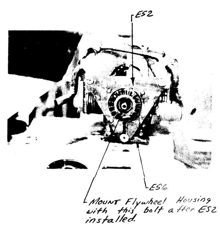
ES2 & ES6
Begin by removing ES2, the 1/4” triangular engine mount, from the aircraft.
Using the ES2 center hole (1/4” diam.) that you previously drilled out, layout a 6" diameter circle, a 5” diameter circle, and a 2” diameter circle. Next, using a sabre saw, cut out around the 6" diam. circle line. Be careful not to damage the area between the 5" diam. and 2” diam. lines.
Finally, make ES6 out of the piece of 1/4” aluminum that you just cutout. ES6 is the Propeller Facing Plate, and is 5 inches in outside diameter, with a 2” diam. hole in the center.
INSTALLING THE ENGINE ON ES2
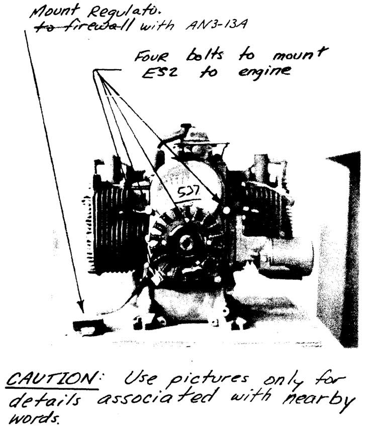
Before the engine can be installed on the firewall, it must be mounted on the ES2 engine plate. Locate the four ES7 spacers, and the four MS20074-05-24 bolts.

Remove from the back of the engine the four bolts shown. Next, using a spacer between the engine and ES2,assemble the combination with the MS20074-05-24 bolts, Torque the bolts to 10 ft/lb (i.e. 120 in/Ib) and safety wire the bolt heads to the ES2 plate (suggest two #30 holes next to each bolt hole in the ES2 plate).

IGNITION COIL MOUNTING
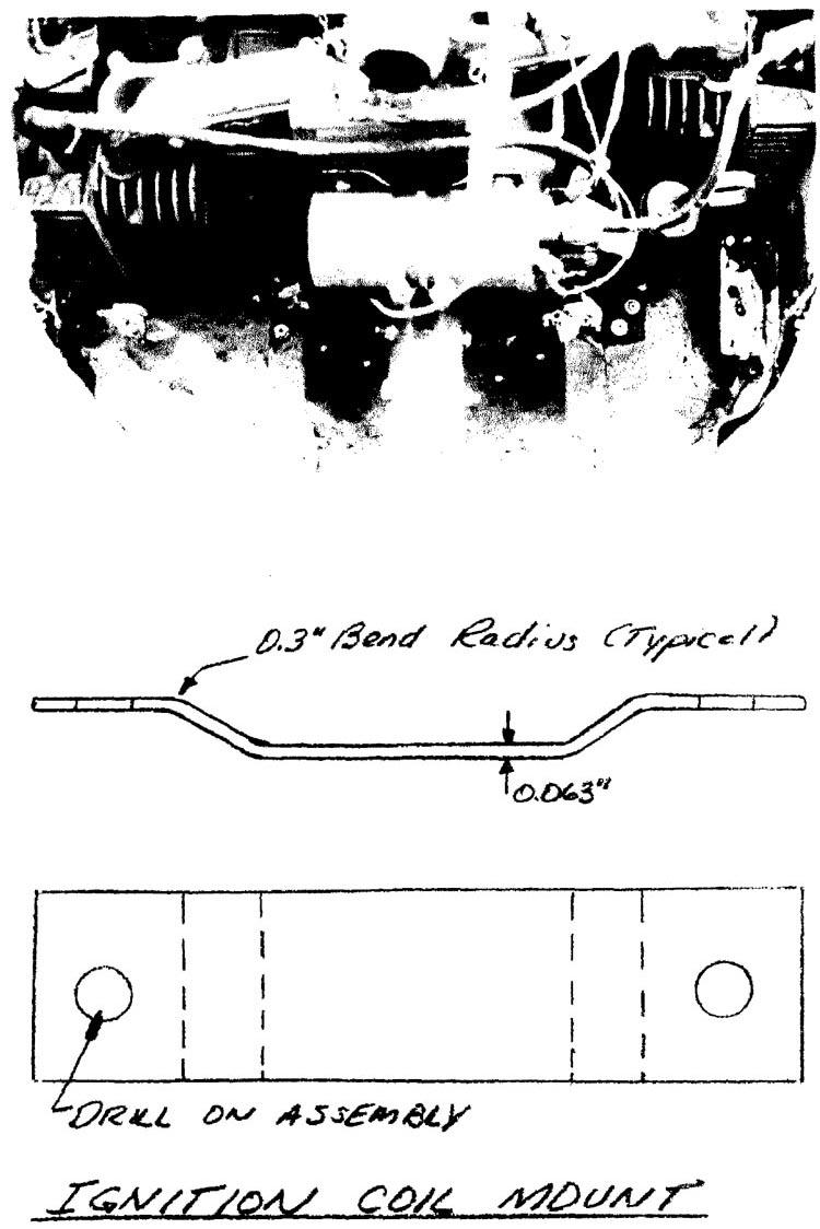
The ignition coil mount is fabricated from .063” x 1” x 4.5” piece of aluminum, as shown. The two mounting holes are drilled upon installation,
The ignition coil mount is attached to the front of the engine by picking up two bolts in the engine block, directly above the front bearing casting. These two bolts are painted red, but should not be confused with the other red bolts that are used for baffling. Two QS100-M32W hose clamps attach the coil to the mount.


