Q1 Plans Chapter 17 Page 17-5
- Details
- Category: Quickie Plans
- Published: Monday, 12 May 2008 10:28
- Written by Dan Yager
- Hits: 2229
PROPELLER INSTALLATION
The ES1 prop extension comes drilled for installation on the engine crankshaft. It also comes with the six prop bolt holes.
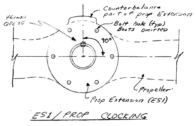
The first step is to drill the prop holes using the ES1 holes as a guide. The best way to do this is to clamp the prop to the ES1, drill one of the holes through, then put a bolt in the hole and tighten it up. This will hold the prop in the proper position in relation to ES1 while you drill in the remaining five holes. It is very important that the counterbalance portion of the ES1 be oriented as in the sketch; it should be 90 deg. plus or minus 5 deg to the propeller axis.
Once the prop holes are drilled, you can take the ES6 plate and drill those six holes in the same way.
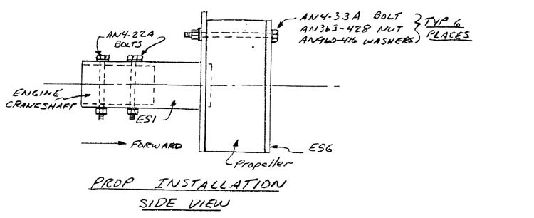
AN4-33A bolts join the sandwich together. the sandwich consists of the ES6 plate, the prop, the ES1 prop extension.
The ES1 is mounted to the engine crankshaft with AN4-22A bolts.


FITTING THE COWLING
The cowling must be fitted and installed after the engine is installed on the firewall. This is so that the cowling can be trimmed at the firewall edges to allow a minimum of 1/4” clearance between the aft face of the propeller and the forward face of the cowling; i.e. you don’t want the propeller rubbing against the cowling!
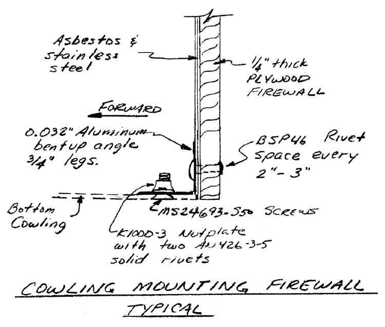
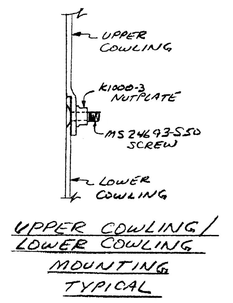
Bent up angles of .032” aluminum are riveted to the firewall. The cowling is joined to these angles with nutplates and screws. The accompanying sketches detail the cowling installation.
You may find it easier to fabricate a template to slide over the prop shaft so as to support the front end of the cowling while you fit the cowling to the firewall.


