Gall Wheel Alignment


- Details
- Category: Q-2/Q-200 Plans
- Published: Tuesday, 30 December 2014 16:21
- Written by Sam Hoskins
- Hits: 31435
LEGAL DISCLAIMER: This document is provided as an incomplete record of events to inform those who may desire to construct similar parts. This information is not intended to serve as design advice. Author does not warrant that it is complete, comprehensive or accurate, or commit to its being updated. You agree that making this information available shall not be seen as the provision of design advice, and therefore I, my heirs, employer, and/or any other agent acting on my behalf are not liable in any way for its use or for the consequences of any actions taken on the basis of the information provided
[EDITOR’S NOTE: The text below is an attempt to improve the instructions for installing the wheel pants on your Q2 or Q-200 aircraft. The text and photos below are a combination of the original text and photos from LS(1) 0417 MOD CANARD construction documents provided by Quickie Aircraft Corporation. I have also included text and drawings from the Q2 and Quickie Plans when referenced, as well as construction notes provided by a builder as he reconstructed his canard after an accident.
During the reconstruction of his canard, this builder also implemented the David Gall Wheel Alignment before mounting the canard to his airframe. It is highly recommended that you read the David Gall Wheel Alignment document before reading the following. Proper wheel alignment has been shown to significantly improve ground handling of the Q2 and Q-200 tail draggers. (Ground handling was a major problem with the original design, and was a contributing factor to some of the design’s bad reputation early on.) The text and images are provided for informational purposes only. Please read and understand the LEGAL DISCLAIMER above before attempting to use this information in your own design.]
WHEEL PANT/TIRE/WHEEL/BRAKE ASSEMBLY
INTRODUCTION
Here you will make one left wheel pant and one right wheel pant, complete with wheel, tire, and brake assemblies.
The wheel pants are composite structural shapes that must transfer all landing gear loads into the canard. Therefore, they are made much stronger than the ordinary cosmetic type wheel pants found on many homebuilts. There is some carving required, but you should find it straight forward.
Note that these pants are designed to fit the standard tires only.
BASIC ASSEMBLY
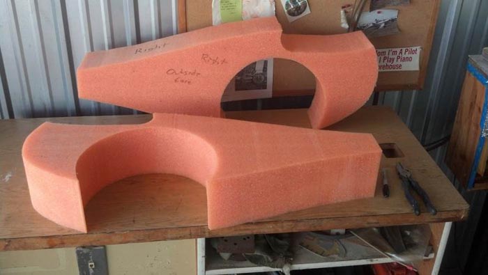
Begin by making two wheel pant cores(LGl)and four wheel pant Covers (LG2). The procedures that follow cover assembling the left wheel pant. Since the right wheel pant is a mirror image of the left wheel pant, you will probably find it easy to assemble both wheel pants simultaneously.
Join LGI to LG2 with micro-slurry. The template sketch for LGI shows the outline of LG2; basically, LG2 covers up the hole in LGI. You may need to use some weight to hold LG2 to LGI until they are cured.
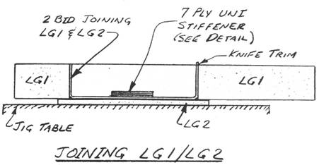
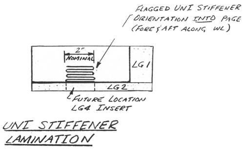
Once the combination has cured, lay it face down on the table with LG2 against the table. Laminate the plies shown in the sketch.
Note: This builder elected to install the LG4 insert before receiving the UNI flagging, detailed below. He also added an additional plywood insert on the inside face of each wheel pant to accommodate the brake mounts.
Now, you are ready to flag the UNI stiffener over the future location of the LG4 inserts. The stiffener location is shown on the LG2 template drawing. 0 Begin with a piece of UNI cloth 14" x 7” with the fiber orientation along the 7" edge. Flag the piece 7 times along the edge (i.e. every 2"). Flagging consists of the following procedure:
|
1. |
Fold the cloth over on itself. |
|
2. |
Wet out the cloth. |
|
3. |
Lightly run a new razor blade across the bubble at the edge. |
|
4. |
Stipple the cloth down. |
|
5. |
Repeat steps '1-4 as many times as needed. |
|
|
|
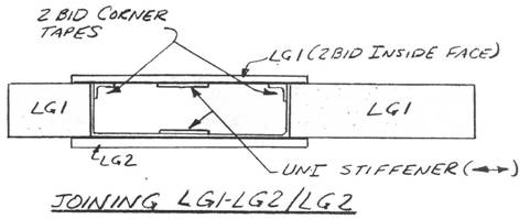
While the layup is curing, take a second LG2 and layup two BID on the inside face (i.e.) the face that will be inside the LGI cutout when it is attached. Roughly trim the glass so that it doesn't extend beyond the edges of LG2, but don't be concerned if you trim somewhat inside the edges. Flag a UNI stiffener to this LG2 just like you did with the other LG2, remembering that the stiffener is on the side of LG2 that will be inside the LG1 cutout when LG2 is joined to LG1.
While the second LG2 layup is still tacky, join the second LG2 to LGI with micro. Now, layup two BID tapes on the inside to join the LG2g1ass layup to the LGI glass, as shown. At this point, you should have a sandwich, with one LGI as the core, one LG2 as the outboard face, and one LG2 as the inboard face. Allow the assembly to cure.
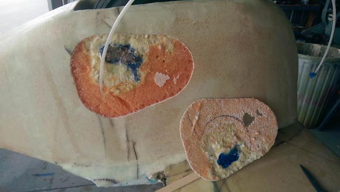
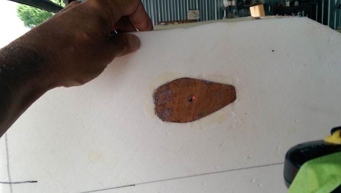
Next, the two LG4 inserts must be bonded into position. Remove white foam from the outside of each LG2 down to the inside glass layup in the areas on the LG2 template drawings which denote the LG4 inserts locations. Then use micro to bond in the LG4 inserts.
After these layups are cured, drill in the pilot holes for the axle with a long 1/8" drill. (Do not use as called out in the original plans). To do this, with the wheel pant lying flat on the table, drill through both faces, keeping the drill perpendicular to the pant.
Laminate 1 BID along the top of the wheel pant where it will come into contact with the canard spar or canard lower skin upon assembly. Be sure that the match between the wheel pant and canard is good prior to glassing, to avoid using considerable flox to fill the voids. Peel Ply the lamination.
Building and installing Wheel Pants using the Gall Alignment and Coughlin Brake Mount
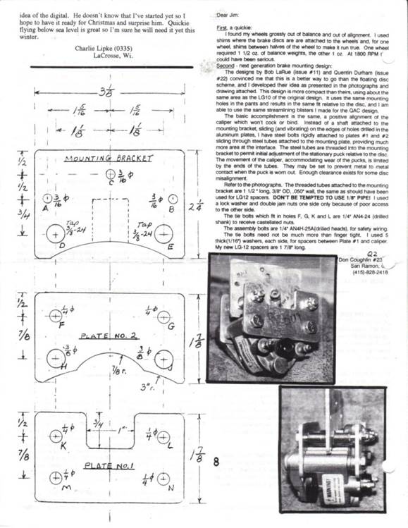
Before starting this procedure, read David Gall’s Wheel Alignment paper and build your brake mounting parts. NOTE: Refer to Coughlin brakes Q-Talk #27, page 8.
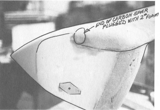
To accomplish the Gall Alignment, we want to sight through the center of our wheel pant, so it meets the opposite side 16.75” lower and 2” forward of the opposite hole. (See crude sketch below.)
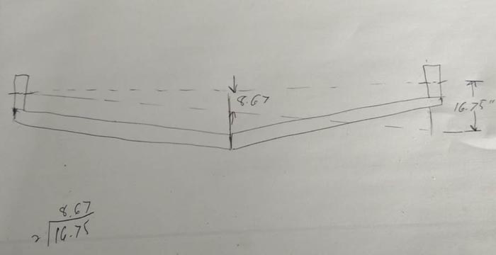
Since we can’t see through the canard, we will use the center of the canard as a target, and divide the numbers in half. The first thing we have to do is to set up the laser and the center target.
1. Ensure your canard is level, tip to tip.
2. Both pants should have the inboard and outboard faces installed, the axle support bonded in place, all interior glassing accomplished, and a 1/8”” pilot hole drilled through the center of the plywood axle supports. The pilot holes must be perpendicular to the wheel pant.
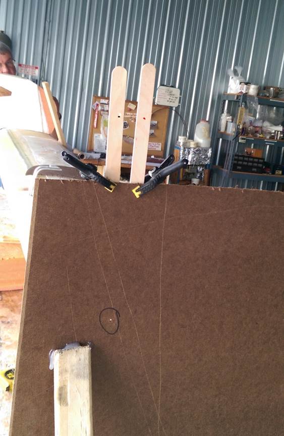
3. Mount a laser on a tripod and place it at least two feet outboard of the wheel pant. You don’t need anything fancy, a cheap laser pointer taped to a tripod will suffice. Just make sure it can’t move.
4. Dry trial-fit both wheel pants in place to attain preliminary parallel alignment. Position the laser and the wheel pants so it projects through all four pilot holes. Temporarily tack in place with small dabs of hot glue. This sounds simple, but it may take a while. A helper will be invaluable.
5. Position a thin piece of Masonite at the center of the canard, so it is about an inch below the path of the laser. Hot glue it in place. You might want to support it with a gusset or something since it is critical that doesn’t move.
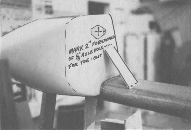
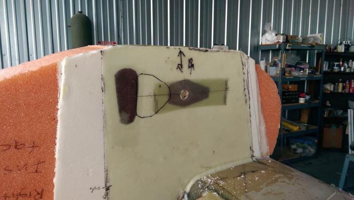
6. Place a stir stick in the path of the laser, so the beam hits the center of stick. Now, place a second stick, one inch forward of the first and make a dot on it, exactly 1” forward of the laser dot. This established our 2” toe-out.
7. Now measure 8.67” straight down from your new toe-out dot and drill a 1/8” hole in that exact spot. This establishes our 16.75” camber.
Now you can break the wheel pants free from the hot glue. To align the wheel pants, position the laser and the wheel pants so the beam passes through all three holes, the outside LG4, the inside LG4, and the hole in your Masonite guide. When you accomplish that, you may install the pants per QAC plans. Once the pants are solidly mounted, you can carefully open the axle holes to 5/8” to accommodate the steel axle.
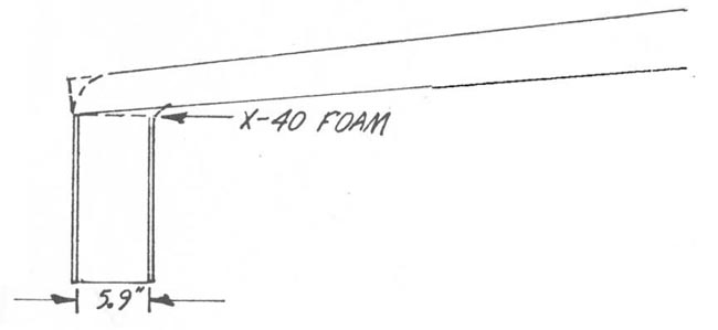
To fit pants to wing, you may want to fill taper with X-40 foam.
At this point you can either carve the wheel pants, per QAC plans, and glass, or you can additional foam for better aerodynamics. If you are going to make the pants per plans, first carve the paint to suit, then reinforce as shown in the step below. If you decide to make aerodynamic pants, first add the reinforcement as shown below, then skip down to the wheel pants addendum. This will provide a strong inner structure without having to modify the brake parts.
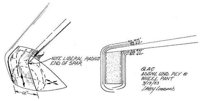
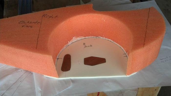
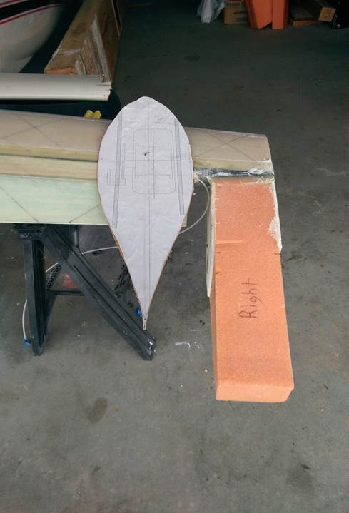
Several templates are provided to visualize what you want the finished product to look like. The templates are provided to help, but use your eyeballs to develop a pleasing shape. Some points to remember are as follows:
1. LG4 should remain .250" thick at the axle hole.
2. A smaller pant will be lighter and cleaner looking, so don't leave excess foam on the pant.
3. The top canard skin will be sanded back for 5"-8" to provide a pleasing, curvaceous contour.
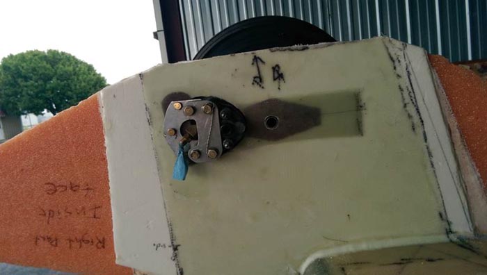
Once the wheel pants are bonded to the canard, attach as shown.
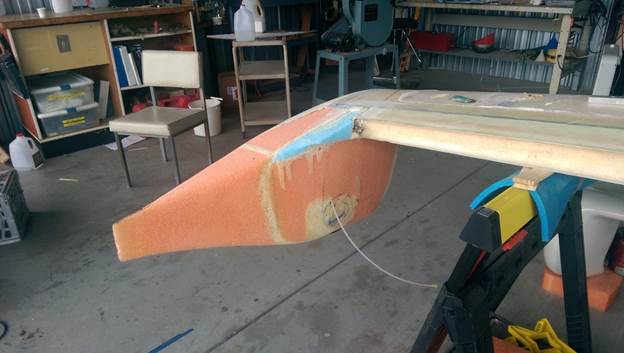
The photo below shows the upper surface beveled and reinforcement glass applied.
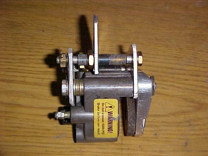
Whichever route you choose, it’s now time to install the brakes. The Airheart brake mounts have gone through a few iterations. The QAC brake mounts were prone to twisting and weren’t very good. Next came the LaRue modification which was leap years ahead of the original. Finally the Coughlin brake mounts improved on the LaRue brakes, and that is what is presented here. The mounts first appeared in Q-Talk #27. NOTE: Refer to Coughlin brakes Q-Talk #27, page 8.
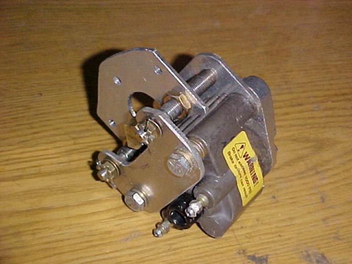
End view of the brake. The center plate, extending upwards, mounts to the wheel pant. You can see the hollow threaded rod which slides along the 1/4" bolts.
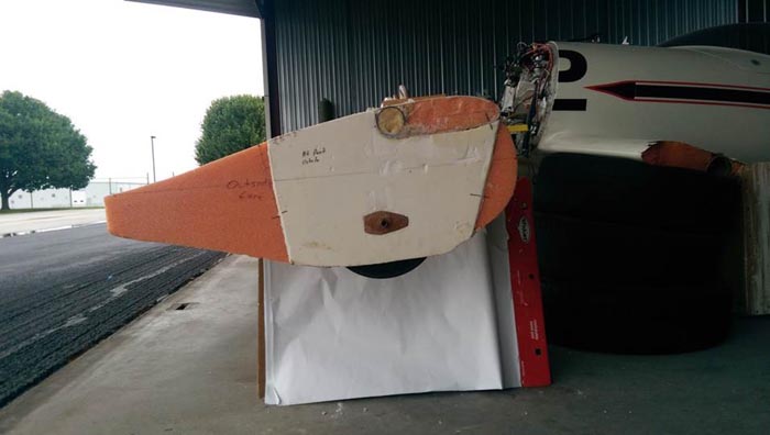
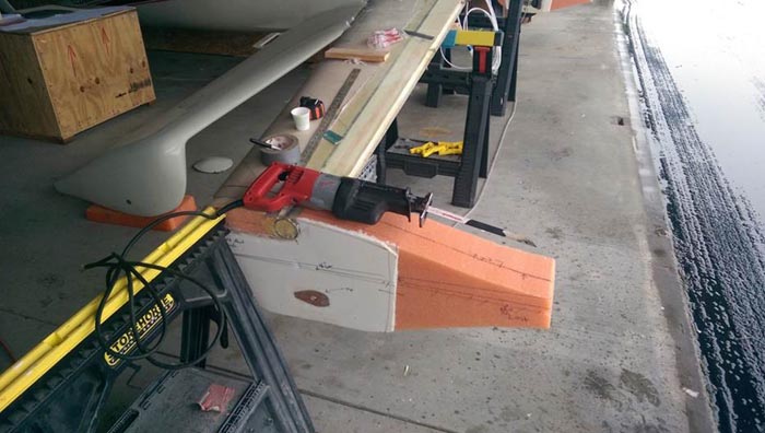
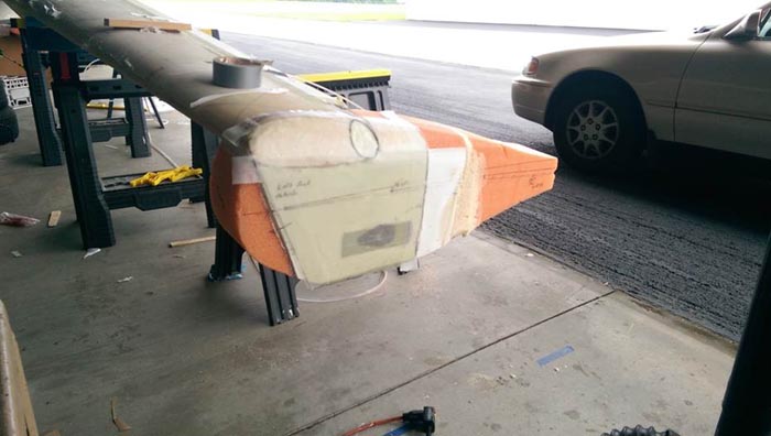
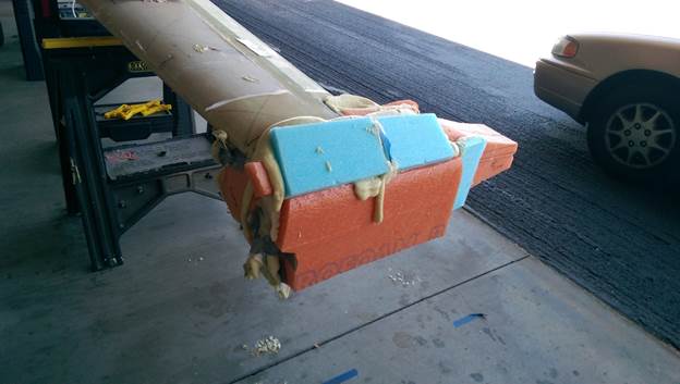
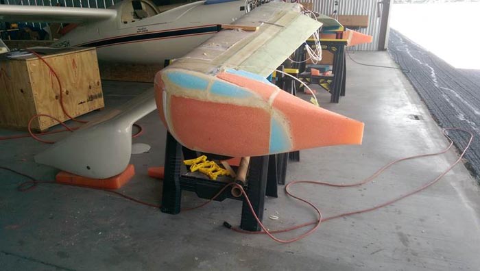
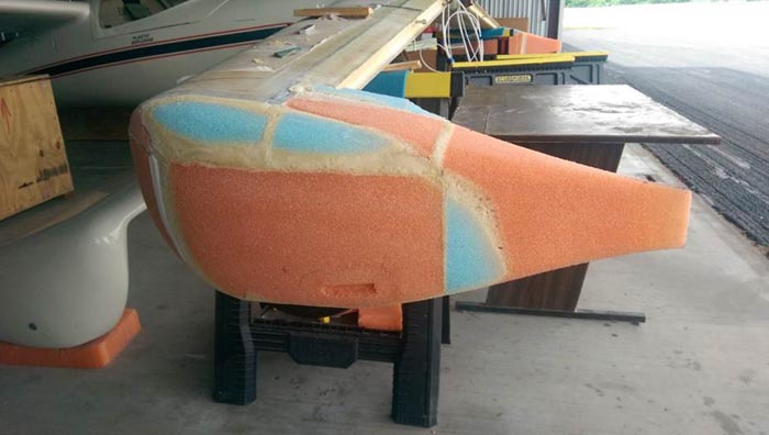
I elected to give the wheel pants a more aerodynamic shape by adding more foam and carving to create pressure recovery style wheel pants. It was simply a matter of attaching scrap foam with two-part expanding foam, then carving to shape. I left the brakes in place, taped over them, and then applied the foam right over them.
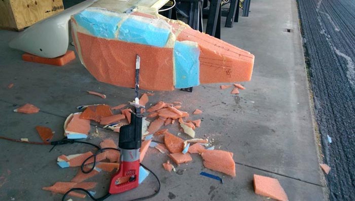
On the inside face, I carved down until I reached the brakes.
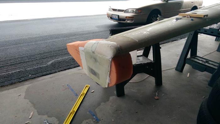
A ¼” steel plate was embedded for a removable tie-down attachment point.
The tie-down loop is threaded into the plate when needed.
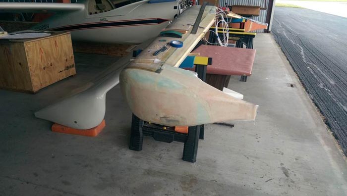
Once the final glass was complete I cut out the skin to use as brake covers. Most of this foam will be removed and nut plates will be installed to hold the cover.