Q-talk 30 - LETTERS - REPORTS - TIPS

- Details
- Category: Q-Talk Articles
- Published: Thursday, 31 October 1991 06:11
- Written by Jim Masal
- Hits: 3183
From Jon Finley, MT
To Manny Lewis and any others with an untraceable oil leak. I have a Dragonfly friend (HAPI 1835) who had the same problem. Turns out he had a super fine crack towards the center of the flywheel that was causing his problem. I don't know enough about these engines to try and explain that - just wanted to pass on the information.
Dear Jim:
David Gall's letter in the July/August Q-TALK finally got to me. Up to then I had tried different baffles and sealers in an attempt to keep the CHT in the green. I had a radiator engineer from one of the auto companies and a A&E look at the aircraft. They were long on theory but no recommendations. As an aside, on page 123 of the Voyager by Yeager & Rutan they discuss the cooling problems they had because they followed basic formulas which were flat wrong.
On the Q, the right side was indicating 450 to 500 on climb and around 400 level. The left side was about 50 degrees cooler. Surgery was called for. Yarn was taped over much of the leading part of the cowl and the engine run. Air flow was observed and the areas of incision were determined. I cut a 2x2-1/2 in. square out of the right front of the cowl and a 2x1-1/2 out of the left side. This incision was just above the belt line and toward the center so as not to interfere with the baffling. Air scoops were glassed on the outside and chambers directing the air horizontally to the horizontal fins on the cylinder heads were glassed on the inside. Also installed were small baffles on the front floor of the regular baffle forcing air through the fins and not letting air pass under the fins.
Results: With 1.5 hours of flight. The right CHT stays well under 300 level and under 350 in sustained climb. The left side runs about 25 degrees hotter.
Conclusion: The right port is too large and the left is too small but not by much. The CHT's are acceptable. The plane flies. To be determined is the drag penalty. Michigan weather is keeping Q9832 on the ground, probably for the winter. I realize that these remarks are premature but they may have value in further discussion about cooling.
Steve Stasinos, RR1, Box 190F, Rapid City, MI 49676
Dear Jim:
The Sept/Oct '91 issue was another super newsletter! The builders are contributing outstanding letters and tips. Well -- it's super stuff to me -- one of those guys that couldn't spell fiberglass when I started my Q-2 and knew nothing about VW engines (still not much). As a result of this newsletter I can spell fiberglass and know a little more about VW engines. My thanks to you contributing builders and to you JIM for running this railroad.
The tire problem for Q-2's will continue to get worse (Ref 4.00 x 5 Cheng Shins). The local dealers selling Cheng Shin tires and who have the current catalogues don't have a listing for this tire!! Obviously we are dealing with a discontinued product. Probably the end product of the production management expertise exhibited by the defunct QAC. I ordered a set of tires and tubes from WICKS (Cat. #TRB 100%-055). They are 4.10 x 3.50 x 5--4 ply. A critical point is that they are 4 ply. The 2 ply tires sold in Go-Cart stores have a max inflate pressure of 30 psi, which is not enough. I carry 32 psi in my tires. These WICKS tires are flat tread but I have not experienced any ground handling problems. However, they are lower profile, which may be a problem if your wheel covers provide limited ground clearance. This lower profile may cause a slight change in the ground angle of attack for the canard and main wing, but I felt that fell in the category of warts on a gnat's gluteus maximus.
To Manny Lewis -- the persistent oil leak from your 2100DQ is probably one of those mysteries that will bug you until hell freezes over!! I have the same problem, had it from hour one and it remains now at 220 hours. Recommend you keep a close check on your oil level and carry a wipe rag at all times. I would like some of you VW engine experts to write in some comments and/or tips on this persistent gremlin.
Fred Wemmering, 5317 Maryland Dr., Fayetteville, NC 28311
(919) 822-2224
Dear Jim,
Since it is dues time I will send you a few photos just to let you know I haven't given up on the tri-Q. The new shop is finished and although I still spend over half of the time at sea I have been making recent progress. The Revmaster is on the test stand and doing very well except for the Revflow carburetor. The engine loads up in mid-range. All cylinders are wired for CHT/EGT and the temperatures look good. Perhaps later I may take the engine and stand up to Revmaster and go through their needle collection.
The main objective at this time is to finish the wing and then go on to the canard. The fuselage is about 75 percent complete and is about ready for mounting the wing and canard.
All of the pertinent items in the QBA news are reviewed just prior to commencing a new phase of construction and they have proven to be very valuable.
One approach I am using to keep the cloth arranged properly while making the layups is to use the yellow mesh drywall tape along the edges and occasionally through the middle of the larger pieces. If the tack is too much the usual trick of sticking it to a clean table and pulling it off solves the problem. The tape is put on before cutting the cloth so that half the tape ends up on each side of the cut line. This helps to line up the cloth edge for the next panel.
As for the test stand, it is working very well. I outlined the firewall and the instrument panel on the plywood panels and positioned the panels the same distance apart as in the aircraft. The fuel tank is mounted so as to produce the same outlet height as the header tank. This way I will have a good idea as to where each firewall penetration will occur. Some small wheels on the heavy end of the stand help to move it around.
Jim, I want to thank you for hanging in there with the QBA newsletter for all these years. Hopefully you will still be there when I get to the flying phase. (ED. NOTE: I hope I'll be there too, Bob.)
Robert K. Lockwood, Jr., 337 La Cresta Hts. Rd., El Cajon, CA 92021
ED. NOTE: Seems to me that we haven't spent much time of late talking details of the 2100DQ engine. I'm not an engine man, but I have been an avid reader of the articles in the KR NEWSLETTER by fellow Texan Monte Miller. The KR guys are almost exclusively VW powered and Monte seems to be especially savvy with the installation. In the hope that some of the KR-VW tips are applicable to our own VW based engines, I'm going to include some of the good stuff that editor Earl Teporten has been printing (KR Newsletter, P O Box 579, Lakeville, MN 55044).
A BAFFLING SUBJECT
Confession time. I don't know about other KR builders, but when I visit a homebuilder working in metal, I get envious of those neat cleco fasteners holding the various aluminum pieces in position while patiently waiting for a few strokes from the rivet gun. The porcupine look has a way of saying, "work in progress".
So, needless to say, when it came time to install the baffle system under the cowl of my KR-2, I immediately went out and bought a couple of dozen clecos and a pair of those funky pliers. If you're anywhere close to cutting aluminum, you'd better do the same because you're gonna need them.
I'm using .032 aluminum for the baffle building. 2024 or 6061 will work. The 6061 forms well and doesn't crack as easily as the 2024. A slightly lighter gauge, like .025, would work but the added stiffness of the .032 help keep everything firmed up. The various pieces can be easily cut from the aluminum sheet stock using a saber saw with a metal cutting blade. Final shaping requires aviation snips, a nibbling tool (found mine in a hardware store), a hand drill and your file assortment. The required bends can be accomplished using some scrap hardwood, C-clamps and a mallet. A bending brake is a luxury, if you have access.
Patterns are best cut from manila file folder stock and test fitted prior to cutting metal. It's easy to tape additional cardstock to a too small pattern or move a hole to fit a manifold but I've found it next to impossible to stretch aluminum after cutting it a half-inch too short. Go slow here and you won't disturb the neighbors at 1:00 a.m. with your yelling. Fine tune the pattern, build the metal part and proceed to the adjacent part. Work for a tight fit against the engine thereby avoiding excessive cooling air loss.
The cylinder "trays" are the easiest parts to form and the best to begin construction with as they help to anchor most of the other baffle components. Use the clecos to temporarily hold each successive baffle panel to the next as you work through the cut and fit. Ultimately, rivets, screws with Tinnerman nuts, or nutplates will be installed. Remember, the baffles have to be removable.
The outer perimeter of the baffle system must seal against the cowl in order for the unit to function as designed. Aircraft baffle fabric is attached to the edge and left long enough to form a rolled seal against the cowl interior. Air pressure generated during flight will aid in sealing the baffle fabric to the cowl. Avoid any metal to cowl contact as the engine's normal movements during operation will eventually cause premature wear and damage.
My particular engine is a basic Volks 1835 with Diehl case and the aircraft utilizes the Rand premolded cowling. The most trying part of the baffle construction is the development of the patterns. If any builder would like copies of my baffle templates with instructions, check out the classified ad section of the newsletter. You'll save time, aluminum and some bloody knuckles.
Monte Miller, 1900 Parkside Drive, Denton, TX 76201
ED. NOTE: As long as I'm robbing tidbits from other newsletters, the Dragonfly Builders and Flyers Newsletter (1112 Layton Drive, Olathe, KS 66061) has had some noteworthy items of interest which I will print here. "Spud" refers to editor Spud Spornitz.
From John Smart, Reading, MA - Here's something that I wasn't aware of and I thought it might be helpful to the gang. I goofed and made a mix of 1 to 1 Alpha Epoxy & glass balloons to use as filler for the weave. However, 24 hours later or better it was balling up on the sandpaper badly. I got it smooth but it was always tacky to the touch. Alexander Aeroplane Co. had an ad in the June Sport Aviation saying to call Ralph Bradshaw with any composite questions. Called Ralph and he told me to wash the tacky part with warm soap & water. What was on the surface was uncombined stuff. I did exactly that and it worked excellent. I'm very grateful for his advice. See everyone at Oshkosh. - John Smart
From Justin Mace of Tucson, AZ - I have been contacted by a builder about testing his fuel tank for leaks. He said that someone recommended that he use air pressure and soap to test for leaks. Sounds good, a lot of leak tests are performed by a pressure and soap method. However, if you stop to think how many square inches of surface area are on the inside of the standard DF fuel tank, this method of testing could be very dangerous for the tank and maybe for any bystander.
The DF main tank is 19.2" x 42.5" on the bottom. This totals 816 sq inches. The top is 12" + 4.4" + 4.6" + 5.6" = 26.6 x 42" or 1117.2". The ends will add another 190 sq inches. 816+1117+190 = 2123 square inches interior surface area. Some folks have a much larger tank. If by accident 5 psi were to get into the tank (is the test gauge super accurate) then the interior of the tank will be subject to a pressure of only 10,516 pounds. That is a lot of needless stress on a part that will never see that kind of stress in flight. A full tank of gas weighs only 78 lbs 78 x 10 G's is 780 lbs.
From Bob Verriest, Allen Park, MI - Spud, you had some questions on Cabin Ventilation. I've never been happy with ventilation on hot sunny over 90 degree days. When below 120 mph IAS you can sweat to death. I added a l inch diameter tube to the front of the engine pointing out the front of the engine cowling. This was used to cool the electronics and works just great, lots of air for the radio, no noticeable increase in engine noise. I thought of adding a larger tube 1.5 to 2 inch diameter for cabin ventilation, however, figured this might not be a good idea. Wouldn't this rob the engine of too much cooling air? So instead I made 2 little aluminum air scoops and added them on top of the NACA scoops. They stick out .5 inch and are as wide as the NACA scoop. They look ugly and are very draggy but they work very well. Can't really tell if they slow down the top speed. Also enlarged rear exit hole to .75x3.00 inches.
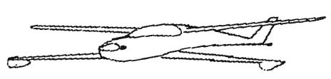
Bill Bertrand found this interesting tidbit in an American Modeler magazine. Floats???????!!!!!
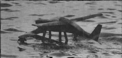
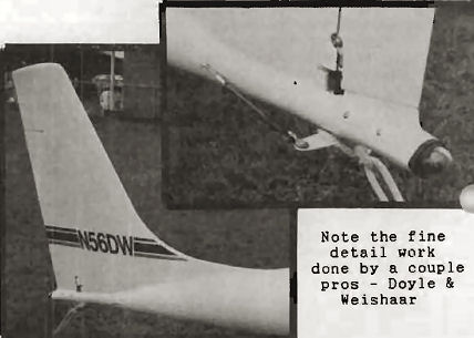
Above: In keeping with the Desert Storm theme, Phil Babben of Napa, CA, brought a "Camo-Quicky" with pylon and tip floats.
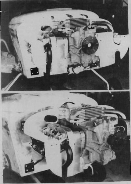
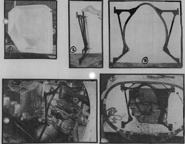
The photos below show the engine swing-away mount that Dick Pratt is operating on his Q-200 N2192D. Photo 1 shows the metal and removable magneto pan. Photo 2 shows a side view of the mount, which is only a width of about 3.5 inches. Photo 3 is the full mount, face on, constructed of 4130 steel, double strength. Photo 4 is a good view of the engine in it's swung out position (careful planning of the aluminum mag box was necessary to allow the engine to swing out properly. Photo 5 shows the mount installed on the firewall sans engine. The mount is attached to the firewall via .060 steel mounting plates, 4 on the front and 4 on the back. I'll need to pester Dick for details of the hardware and brackets at the 4 firewall attach points and the exact hardware setup for the pivots. Stay tuned.

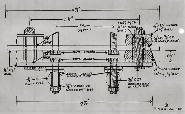
Ed Miller of the Chicago area had a very successful Rotax 447 installation in his Quickie. Here are some of the details of how he shock mounted the engine:
This is the shock mount system used beneath the engine. You'll need two set-ups like this, one front and one rear. The rubber donuts were simply cut from 1/2" sheet stock of neoprene. The rubber around inner steel sleeve inside donuts is stock rubber tubing cut to length. Durometer on the rubber sheet is 55. I got mine from Ace Tube and Rubber on S. Wabash in Chicago. Shouldn't be too much trouble to find. You may need an additional 1/8" washer under lower rubber donuts to keep inner bolt heads from knocking together. Space as necessary. Any nuts near the muffler should be of the steel locking kind rather than those with nylon insert to avoid meltdown. Weld up the horizontal portion of the bed mount first (making sure all is symmetrical) then use the engine as a template to lay out holes in bed. The same spacing applies to shock-mount system (below).
Dear Jim,
I had a guy from Huntsville, AL stop in on his return flight from Kansas City, MO in his Rotax powered Quickie. He surfed in on the leading edge of a nasty front just before dark. (Actually it was already kind of dark.) He had just spent several hours of flying in and out of rain showers (without vortex generators) and scud running down Main Street of several towns. This was about a 1000 mile round trip. Apparently no one has explained to this guy that you are not suppose to use these things as real airplanes.
David Fulper (601) 236-4684
ED. NOTE: That masked man is Chris Barber in a Rotax Quickie who in reality is a Dragonfly buff who decided he could get an abandoned Q into the air first while he worked on his DF.
I am continuing to flight test my Quickie. I have 20.5 test hours on the bird and 95 landings. After each test flight, I check everything to make sure all is good.
I have had to change my CHT gauge because of erratic readings. The altimeter provided is NG either. The vibrations move the dial. I use a rubber band around the adjustment knob to hold it steady.
The main reason for this letter is this. I am badly in need of 2 tires, size 4:00 x 5 with overall outside diameter of 12+", load rating B, 4 ply, 50 psi pressure. Chang Chin brand if possible. These are supposed to be the grass field tire.
Maybe some QBA member has these special size tires and does not need them anymore. I have tried nationally and internationally to get them with no luck, so far.
I've done extensive taxi testing prior to lift off so the rubber wore. I reversed the tires to wear the other edge and that's also nearly all worn off.
The break scrubbers are made for this OD tire. A small tire 4:00 x 11" would cause a lot of additional work and would not be as good.
I shortened my last flight to 1 hr 12 minutes because the oil pressure started to drop below 25 psi and the oil temperature started going up from 200 to 225 degrees. I still have to investigate this. I'll fly over air field to recheck these 2 gauges after I thoroughly recheck the engine.
My A/S is NG and I've excessive RPMs when flying level. Am getting another 44" prop made with a 29-degree pitch rather than the 27-degree pitch. Hope it works better. My current A/S, level flight is approximately 85 to 95 MPH. Not good at all, yet my prop winds up to 3700, 3800, 3900 RPMs. Much too high.
In my last trouble letter to you I had damage to the top skin of the canard due to hard landings. This was corrected and the top canard (LS-1) was reinforced with additional UNI directional plies. (Ditto left wing) From the leading edge bottom to over the top to the elevator. Everything is looking good.
I mounted my Sporty A 300 H/H radio to the right side canopy hinge plate fiberglass strip. Everything is now working great with nothing dangling around me.
I made an oil breather hose breather jar so that no oil slick would be spread on the bottom side of the fuselage. The oil breather hose ends up in the plastic oil collection jar.
I used Amsoil oil after the break in mineral oil. The Amsoil was quickly replaced as it started to seep out the thrust plate bolts heads and then the oil pan gaskets and then the oil filter cap. Oil everywhere.
I resealed the thrust plate bolts with Permatex and I used an epoxy mix painted over the oil pan assembly seam. Remade a "cork" oil filler plug and so far, the oil is staying where it should. That's all for this Sunday morning.
I need the tires badly. Hope that through the membership I can get assistance.
Thank you, Ted Kibiuk #508
ED. NOTE: Remember my admonition in the last newsletter about engineers (i.e. you are not building a space shuttle or a gnat's ass)? Remember I said nevertheless to learn from these guys? Well here's the flip side of my tune and it's about eyeball engineering.
Now I'm not picking on Ted here because I know not all the travails and deliberations through which he arrived at his top skin fix. He has historically been quite careful, BUT ... we learned many moons ago in these pages about stress concentrations that can occur at the abrupt end of a ply of cloth and that should always be considered when you are working with skin layups.
And on changes in general, while we may reinforce or change the design of what doesn't "feel" right to us, we should always be acutely aware that the plane was designed as it was for very good reasons and that we may make a substantive change at great risk. Airplanes are sometimes SUPPOSED to break at certain places to protect the occupants or for other reasons. Changes should not be frivolously considered. There is a granite marker now over the body of the first guy who decided that the area over the main wing would be a great place for a gravity feed auxiliary tank. Neat idea, but he didn't consider ALL the consequences.
As you consider any substantive change to primary structure, the hair on the back of your neck should stand straight out from trepidation until you've considered all the angles thoroughly.
Hello Jim,
Here is my 20 bucks for next year and an ad. I would contribute info, but I don't feel this old goat has any wisdom to contribute. How I envy those that are craftsman, but I am stumbling along, and due to the nature of our materials I can redo and cover up my goofs, and at least hope the layman won't recognize it. At least you can't say that I haven't tried to contribute. I was highly impressed with the letter from David Gall in #28, so much so that I am going for the Onan, especially since I only weigh 120, and besides I hope to buy a ballistic deployed parachute. I would appreciate any advice on where and how to install it on a Quickie.
Harold Nelson, P O Box 2153, Orangevale, CA 95662
(702) 988-5055 or (916) 988-3349
Dear Jim,
Positive thoughts for '92 is what we want from you! I think if that hadn't been the case QBA would be gone by now, keep up the good work.
A year in review and progress report for '91 is as follows. I've completed about 75% of the foam hot wiring and this spring should see the rest done. The main wing was glassed this past summer but the trailing edges and ailerons have not been installed. The main gear has the UNI wrap and the seatback bulkhead and gear area have some of the reinforcement glassing done. Seatbelt attachment points are in place. An engine was purchased, a'74 type 4 VW, which I plan to bore to 100 mm and stroke to B2 mm. Looking for a dependable 90 hp.
This month I set a goal for completion - Sun N Fun '93, and that is not that far away. But it's not impossible if I spend more time in the shop and less on the couch watching TV.
Thanks to all for the support you have given to the QBA.
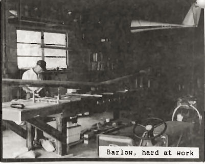
Richard Barlow, Stockbridge, GA
Here's an update on progress:
I finally got the canard attached to fuselage after much messing about. Using female templates I found I have 0.5 degrees twist across the length of the canard. I talked to Scott Swing about this and he thought that this degree of twist would be controllable with trim. I mounted the canard so that the average incidence was about 0.5 degrees nose up.
I just finished glassing the main undercarriage leg (Tri-Q) and mating it to the fuselage. Total time - 70 hours. I still have the nose-gear to attach and the fairings to deal with so I suspect the final time will be significantly above the suggested 50 hours. However, the instructions are excellent and I've long since given up believing estimates of time to build anyway.
Next comes the fuel tank - I still have the fuselage top separate from the bottom (thanks to many Q-Talk tips) so this is fairly easy going.
Total time to date: 570 hours.
Total time when complete (current estimate): 2000 hours.
Keep up the good work on the newsletter - what would we do without it?
Dave Chalmers, Redmond, WA
Jim,
Q-200 N17PF is still flying! It currently has 115 hours and has been flying just over a year. My flying has slowed considerably in the last six months (babies wield unbelievable power!). The only major problem I've had was last February when my plane got an uncontrollable urge to head off the runway and out into a cornfield (taking out a runway light just for good measure). That required repairing the left canard, both wheel pants and the lower cowl. After waiting for a new prop for four months, I got back in the air in late June.
While it was down, I added differential brakes that have helped ground handling tremendously. I simply replaced the single brake handle with two handles (attached where the original master cylinder was) and mounted dual master cylinders on the left side just forward of the instrument panel. The brake handles are attached to the masters using control cable (about 12" each). For just the cost of one more master cylinder (and a little cable), I would highly recommend people put in differential brakes. If the plane starts to head for the corn, a gentle tug on the opposite brake brings it back immediately!
Other than that I've just enjoyed flying it! If anyone's ever in the vicinity of Davenport, Iowa (maybe to do a little gambling on a river boat), give me a call and we'll go for a ride.
Paul A. Fisher, Taylor Ridge, IL
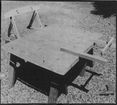
ED. NOTE: At the last Dragonfly Swarming in Sept., I met builder Len Griffin who talked about having to replace a canopy. Since his canopy is constructed similar to ours, I asked and he graciously provided photos and a description of how he made his replacement:
If you should be so unfortunate as to break a canopy bubble, don't despair! It can be replaced without bringing the plane home. A simple jig made to fit the cockpit dimensions will let you do the repair even in your wife's kitchen (if you care to suggest that!). Here's how:
1. Cut a sheet of half-inch plywood to fit over the longerons from instrument panel to the seat rear bulkhead. Mark and cut to match the curve of the outer fuselage sides.
2. Fasten 1" x 4" furring strips to outside edges with wood screws (on bottom) and trim to contour. Also fasten 2" x 2" pieces to ply base both front and rear as shown.
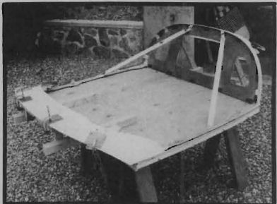
3. If canopy frame is intact or can be pieced together, fasten frame to base with 1/4 x 20 bolts with washers and wing nuts through side rails at four points, taking care to position sides flush with sides of base. Fit rear knee braces and front support to hold angle of rear bulkhead and height of front cover. If frame is not usable, this method could be used to build a complete canopy, but careful measurements will be required to establish the bulkhead angle and front cover height.
4. Remove canopy frame from jig and cut sides of base 1" in from edge using jigsaw. This step is to provide clearance to fit the new bubble since the old canopy is wider by the thickness of the outside fiberglass layup. The width of the saw kerf will allow for this difference. Refasten the cut strips with countersunk flat head wood screws. Drill pilot holes before cutting.
5. Refasten frame to jig. Make small tabs from 1" aluminum angle and fasten two on each side rail in tight contact with inside face of old bubble. Do the same as needed on the rear bulkhead (I used four on each side.) These will be drilled and used with clecos or small screws and nuts to hold the new bubble in place for epoxy bonding to the frame. Also cut and fit diagonal braces from side rails to rear bulkhead to be sure proper angle is maintained when the assembly is removed from the jig for glassing (I used 1" aluminum angle).
6. Carefully remove remains of old bubble, cutting Plexiglas and outside fiberglass layup away on sides and bulkhead, and inside on the front cover. Inserting a broad bladed knife between the Plexiglas and the fiberglass layup that you want to save, and tapping gently with a light hammer worked well for me. Save the piece from the outside of the bulkhead - it can be re-used.
7. Now remove the previously cut sides for clearance, insert the new bubble nose down into the frame, and pivot it so that the rear rests on the bulkhead and the front can be wedged up to fit under the edge of the front cover. Drill and cleco the bottom and rear to the tabs installed in step 5 and trim the bubble as needed. Between steps 6 and 7 it may help to sandwich a strip of thin aluminum sheet between the rails and the jig base, trimmed flush with the outside edge of the rails. This would make a bottom limit in which to trim the new bubble. Put a layer of duct tape on the sides of the base to prevent epoxy from sticking everything together!
8. Refasten the cut sidepieces. Add a 1/4" thick batten to hold the sides of the bubble tight to the frame. May also have to use small wedges. Screw batten on separately from the previously fastened side pieces.
9. When all is fitted, remove battens and bubble, glue bubble to sides of frame rails, rear bulkhead and front cover, refasten all supports, clecos, etc. and let cure.
10. After cure, remove (carefully) bubble and frame from jig and proceed to glass bubble to frame, inside and out as per plans. Glue the fiberglass/epoxy strip that you saved in step 6 back in place on the outside of the bulkhead using clecos to hold in place.
NOTE: As an option, you may want to remove the glass on the bottom of the frame rails prior to step 3. If not removed, canopy will be higher and will need some micro added to the top of the turtle deck to make a smooth transition.
Dec. 20, 1991
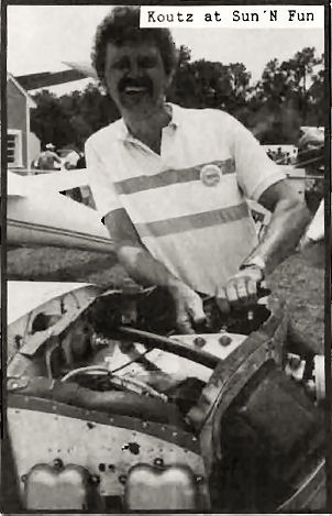
Dear Jim,
Well another year has past and I have a few more hours on the bird. I am up over 100 hours total. I had an alternator problem at Sun-n-Fun that I thought was a loose connection at the back of the alternator but when I pulled the engine to check the connection, it was tight so I pulled the alternator off and found the drive gear teeth had been "chewed" off. The gear in the engine was good. I don't know why the alternator gear failed and I have several theories but the end result was an engine rebuild. The alternator was homebuilt. It consisted of a spectrum or spring car alternator mated to an adapter plate that bolted to the 0-200 generator pad. A short shaft screwed on to the alternator shaft and held the drive gear. This combination seemed to work great but since it was an experimental setup - I SHOULD HAVE CHECKED IT MORE! I rebuilt the engine and now fly it without an alternator or generator.
Then I decided to work on my high landing speed. I had taken a wedge out of the bottom of the tail cone to get the right angle of attack for the wings and to get the tail the proper distance off the ground for the tail spring to look natural. This resulted in a landing speed of 85 to 90 MPH. I decided I needed more angle of attack on the ground to take off and land slower -- why not. I could fly the plane at 60 MPH straight and level, why couldn't I land at that speed? The end result after putting the wedge back in, getting the two halves of the aircraft fuselage to fair in was that I could land at 70-75 MPH. This was good! What I can't explain is that I lost 10 MPH off the top end and I had higher oil temp. The temperature now runs 210-235 degrees and it is cool outside. My CHT runs about 200-250 degrees. So now I am looking for a way to cool the engine oil without an oil cooler.
I am going to change the angle of incidence of the canard (I fly with 1.5 -2 in of up ailerons to get the elevators to fly in a trail position) plus build a swing away engine mount in the near future. (Before Sun n Fun?) Since the work is all in the same general area, it should be easier to accomplish these two modifications at the same time.
Larry Koutz
ED. NOTE: Pay attention here, this is something we need more of (shoot! I would've ended that sentence in a preposition if I didn't think of this gimmick). Larry did something I just recommended against ... re-engineering the plane. BUT, having done so and having found out it didn't work, he has taken the unusual step of admitting it so nobody else wastes time trying the same thing (taking a wedge out of the forward, bottom tailcone so as to tip the thing down and avoid the oft times funky looking tailspring mods necessary to get the required 7.5 degrees GAA). I'm SURE there are others of you out there who have tried mods but are too embarrassed to say, "aw shucks guys, I thought I had a neat idea but it didn't work. Don't you waste YOUR time on this too". It sure would help us to know. Thanks for this, Larry.
Jim and Friends,
Great news. I've flown!!! Man, was it great.
I received Jinx's 503 on Oct. 2 and went right to work. Everything went right on with minimal modifications. The FAA and myself do not get along here very well so I had to go thru that never ending hassle again. But then this last weekend Nov. 23 I got the balls to go try her out (I'd been ready for almost two weeks). Winds were 060 on Runway 9 and a beautiful 31 degrees. I am using a borrowed Prince 46x52 prop from Bob Bounds and it is not enough. But it sure did provide a short ground roll. I climbed out at 80 and made right traffic doing 90. Man is the Quickie a sweet plane to fly. It was terrific. I made a great landing taxied back to the hangar and ripped off the cowl and inspected every bolt on the plane. Could not find a thing wrong or think of a thing that needed change so I went up and went around again. By this time it was getting dark so I headed home and guess what it did, SNOWED! I haven't even been able to get out of the hangar since. Isn't that the breaks - a plane that finally flies and you get rotten weather.
I did have a lot of radio noise that Jinx had warned me about. I had put steel braid on the plug wires and had two metal plug caps on (If anybody has more they would like to get rid of give me a call.) in an attempt to keep the noise down before the flight. I have since put a metal box around the coils. Will see if this helps. If not California Power System sells a radio suppression system for $70.00. Might try that. If anybody has tried it, give me a call.
If there is anybody out there that has put sparrow strainers on their Quickie drop me a letter or a call. Bob Bounds has put them on his plane and feels that they really helped with stability. If there are more positive comments, I might try them on my plane also.
Here is my $20 for next year Jim. What a great newsletter - keep up the good work. Everyone fly safe and may you all have better weather than I am having!
Jon Finley (406) 449-8872
You can order a PDF or printed copy of Q-talk #30 by using the Q-talk Back Issue Order Page.