Q-talk 19 - LETTERS


- Details
- Category: Q-Talk Articles
- Published: Sunday, 31 December 1989 06:11
- Written by Jim Masal
- Hits: 2722
Jim:
Another year has come to an end and once again I find myself writing you to renew my subscription to Quicktalk. I would like to remind you how much I appreciate your efforts on behalf of all us building Quickie type aircraft. Each issue is read cover to cover upon receipt. More often than not, I am moved to laugh out loud at your outrageous sense of humor! Please keep up the great work.
During the holiday I was visited by Jerry & Nancy Marstall (Tri-Q2 project) of Boston, MA. We had a delightful time hangar flying and discussing our projects. Their visit reminded me again that the very best part of the building experience has been and continues to be the many fine people I have met since beginning the project nine years ago.
Current status on N72PJ is as follows: still down for modification of engine cooling. I had Revmaster rebuild the engine and have received the repaired engine from them. They were very responsive to my questions and are still in business. Based in part on discussions with Allen Horvath of Revmaster and an article on engine cooling in Sport Aviation, I have begun extensive modification of the aircraft from the firewall forward. I have also removed part of the lower firewall in a similar manner to that described by a Quickie builder in Quicktalk this year. I removed approximately 3" of the lower firewall all the way across bottom of the cowling. I then beveled the area to the bottom of the fuselage so that there is greater relief area for the expanded air to exit the cowling. I am currently re-finishing this area and the lower cowling. Once this is complete, I will install the engine and begin re-baffling the engine cowling. This too will be quite different from the original set-up.
As soon as I get further along, I'll send some pictures for the newsletter.
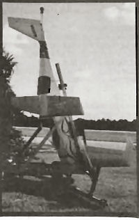
Art Kreutzer's traffic stopping Quickie Transport System.
Jim,
Well we finally had our roll out. Enclosed is a photo of our Q-2, ready to face the world.
It has taken us 6 years of intermittent work to replace the canard, which broke on a high speed taxi test. The pilot lost control of the aircraft, and the wing broke under the stress of trying to go across the rough grass infield, and running into a water drainage ditch.
We had the engine checked out by Revmaster and increased the horsepower to seventy-five. When we finally had the chance to start the engine, it ran real well.
The reason I am writing is that another Q-2 jock with a lot of experience in his similarly equipped aircraft noted some things which must be corrected.
First, we routed the fuel line through the firewall to a fuel pump, and then back to fill the header tank. This routing puts the pump and lines close to the exhaust header. Ken felt that we are just asking for vapor lock, especially if the plane sits a while (half hour) between flights.
And second, we found a product marketed by a turbo charging company that might be of interest to some of those having heating problems under the cowling. This product is wrapped around the exhaust headers and insulates the exhaust system very well. We wrapped the intake system also. The temperatures under the cowl are much lower and the vapor lock situation should be improved.
Thanks for your suggestions for our first flight. I also wrote to Sam Hoskins and wisely spent a $1.00. We hope to be in the air soon.
Please renew my subscription and look forward to seeing you at Oshkosh.
Bill Welsh, Anaheim, CA

Dear Jim,
My Q2 N24H saw no airtime in 1989. In 1988 I completed my fly off and made several trips from Salt Lake City on business. The farthest I traveled was to San Angelo, TX.
Airtime has been most enjoyable, but 1989 was spent fixing a number of problems. The most important problem to be relayed thru the QBA regards the Revmaster ignition system. (I have a turbo Revmaster 80 with the constant speed prop.) I was having a problem where the engine would mag check fine for run up, but during a post flight mag check, one mag would act as if it were shorted. (The engine would immediately stop firing.) The engine would always run smooth as a top on the other mag or the both position. After much effort by my A/E (2 engine removals, retiming, new capacitors, tach wire check, instrument panel forward wiring check) the problem was finally traced to a bad soldering job on the P-leads. Everyone with Revmasters ought to do a post flight mag check as there are no other obvious symptoms.
My Maloof prop was apparently one of the last ones made before the company went under. Their quality control was not too good. The first prop I was sent had a forging flaw. There was a surface void about .050 deep and several inches long. Maloof replaced the blade at no charge.
After I had been flying a while, the blade hub seats just didn't seem right. Since Maloof was out of business, Revmaster said to send the prop assy. back to them. They said that the prop hub was machined .006 oversize. To their credit they traced down the hub forging subcontractor, got a new forging, machine it, reassembled the prop and returned it at no charge. You can't ask for better support than that. It wasn't even their product!
I had Revmaster's dual alternator setup. I decided to switch to a more conventional system to increase the amperage available and to simplify the system. I decided to use the 65-amp alternator that's advertised in the back of Sport Aviation. I had a local machine shop machine a new oil filter mount, an alternator mount, and a new vacuum pump mount. Everything seems to be working fine.
I ended up replacing the turbo charger. A source for these is Turbo City (714) 639-4933. Talk to Jim Sharp. There is a new model turbo with the same external dimensions, which is about 30% more efficient. This should raise my max power ceiling by another 1000 feet. I haven't been able to check it out yet. The old turbo would develop 27 inches at 11,000 feet.
A far better emergency hand pump than the one supplied in the kit is manufactured by Marine Products. They are available from any boating supply store, and they don't leak.
My plane was built by Custom Composite Components. My original contract was for them to construct my Q2 kit per plans, ready to taxi for $10,000 in under a year. Modifications to plans were to be charged at hourly rates. The major changes I asked for were:
Turbo Revmaster with constant speed prop
Enlarged canopy
Dual side sticks and dual rudder pedals
Narco Escort with audio panel
A/H, Turn Coordinator
Insight CHT, EGT, M/Pres, other eng temps.
Lights for night flying
Some things such as the stick positions I asked to be changed after they had been completed as originally requested. Other things had to be redone by Custom Composites because of poor execution. By the time the plane left their hands I had spent over $20,000 IN LABOR. Am I satisfied with CCC's work? No. I have had to spend over a year and several more thousands of dollars for additional A/E work to correct systems, which I and Scott Swing considered unsafe. (Ask Scott about my plane's first flight.) Would I recommend Custom Composite Components to others? No.
Brian Bulaw
Dear Jim,
I have been thinking about the final finishing stage in which it is desirable to roughen the surface without cutting into the glass weave. It seems to me this would be hard to do with sandpaper since you couldn't get down into the low spots without cutting off a lot of the cloth. I've read where sandblasting has worked well for some, but I also wonder about damage to the cloth. Well, I never have tried it, but I just heard about plasticblasting with non-toxic plastic granules. The stuff was developed for removing paint from delicate stressed aluminum aircraft skins. It does leave a texture to the blasted surface, but not nearly as rough, and without the heat buildup of sand or glass beads. The plastic blast media is available from U. W. Technology Corp., 328 Kennedy Dr., Putnam, CT 06260, (203) 779-1401. On wing and canard incidence, I still like D. J. Harms setup described in Q-Talk #2 '87 pg. 4. I'm finding out a lot of these questions have already been answered in the back issues. Thanks for all of your efforts and let's make this year a productive one.
Bill Archer, Magnolia, AR
From Jinx Hawks
I have made a rigging change in the Quickie and will pass it on like all good Quickie drivers should. I noted earlier that I had adjusted the right elevator 1/8th inch lower than the left elevator at the inboard trailing edge in order to reduce the left aileron correction for the Rotax 503's torque. Since then I have carried a little left aileron, but didn't think about it until Howard Hardy said his Rotax Quickie required 1/4 inch of trailing edge down adjustment to fly hands off. No, his airframe is not warped, at least not anymore than mine. I turned the "Dog bone" end fitting 180 degrees to lengthen the dog bone and what do you know? The right elevator is now 1/4 inch lower than the left one the aircraft flies hands off in roll at a cruise of about 110 mph.
I believe that a dog bone length adjustment is recommended for roll trim in the Quickie documents with the Onan engine. With the Rotax 503, it is a very important adjustment. Due to engine torque and the inboard location of the ailerons, you will need ALL of the aileron throw capability in a low speed asymmetrical gust landing condition.
I have just passed the 150 hr. mark on N13VD and both airframe and engine are doing great. I just summarized hours for last year and am very, very disappointed to find that I only flew about 25 hours. This is the fault of a conservation pilot, not the aircraft.
Ed. NOTE: Shoot, Jinx, to fly only a measly 50 hours a year, you'd have to fly once a week, every week, with no time off for good behavior. As of Jan. 23rd, Jinx has sent out 74 info packets on the 503 conversion. Quickie interest is quite alive.
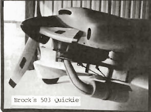
From Norm Howell
When I'm not actively flying my Q there is not as much new stuff to discover. However, it is being flown by a couple of friends of mine and they have sent some tidbits back to me.
As you know, Jim, I had to put external air filters on the Rotax engine to make sure it got clean air. Since the chokes had also been removed, I had to remove the filter before each start and squirt some gas/oil into the engine to prime it. The Rotax won't start very easily when it is cold if you don't prime it or choke it. Recently a primer kit from LEAF was installed. This made cold starting much easier, however, it is now possible to flood the engine since, with the primer valve open (pulled out) there is an open pathway to the carb for the fuel to flow when you squeeze the fuel squeeze bulb also. So here's my procedure for a cold start: Open the primer valve and use the squeeze bulb to prime the engine. Then close the valve and continue to pump the bulb until it gets hard to squeeze... this means the float bowls in both carbs are filled up and the float valves are working properly by shutting off the flow of fuel when the bowls are full. Throttle idle and ignition off, pull a few blades and then it starts on the second or third blade after ignition on.
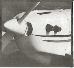
Howell's snorts clean air now.
I would not recommend the 2.00 to 1 gear ratio for the Rotax 503 conversion unless you were after brute speed and did not mind a flat climb. As I have previously written, my combination right now is a dual carb 503 with a 2 to 1 reduction and a 2 blade 46D x 53P Prince prop. This is roughly equivalent to 3rd gear on a Porsche... you go like a bat out of hell, but you are slow off the line. I still don't know how fast mine will go since airframe redline occurs before engine redline and it's still accelerating. Flutter is one of the F words I DON'T want to experience. It is very easy to fall out of the power band if you try to climb too steeply. The engine will go from 5200 rpm to around 4000 rpm, which means you are getting maybe 25 hp out of it. Shades of the Onan! If you level off it will creep up to 4400 then hit the power band and shoot up to 5500 or so, giving you an afterburner-like kick. All this without touching the throttle by the way. This is normal 2-stroke behavior, but may be disconcerting to the new Q-Rotax flier. Under poor circumstances (hot wx, and high airports) I have had it not come up on the power band at all until after I took off, climbed about 50 feet and leveled off to accelerate.
So put the 2.238 to 1 ratio in your planes, boys and girls. McCaman and Hawks use that ratio. You can climb like crazy (1200 fpm plus at 75 mph... a deck angle like a Helio Courier) but still get the top when it's time to run down that Kitfox you see 2 miles away, tail on... and he does NOT see you!!! I will report on the performance differences as soon as I finish having the gears changed.
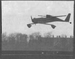
Martin Burns - Just the way I like 'em
I have been corresponding with Martin Burns in Scotland who is changing to the Rotax. Also I have helped Robert Kluge of Landshut, West Germany by shipping a CACI Rotax 503 cowling over here for his Quickie project. Through the German mail system, the $275 cowling would have cost $325 just to ship! Wow...it only cost me $1200 to ship an entire Long EZ! Robert will build the new canard with a self-engineered spar. He will have the help of colleagues from the Akaflieg Munich, which is a college level engineering organization that allows students to design and build light planes, gliders and motor gliders. Each Akaflieg (there are many in the West German university towns) has built and flown numerous original design aircraft over the years since WWII. So Robert is in good hands engineering-wise. (ED. NOTE: Can you prevail on Robert to share any successful spar designs with his American friends across the POND???).
Since I am now building a 70% complete Long EZ, I must regrettably offer my Quickie up for sale to raise money for the EZ's engine. I have not advertised N17OQ anywhere else yet thinking that a QBA member out there might want first shot.
ED. NOTE: Yup, you can advertise it, but no fair taking up more than 5 lines even if it DID take the '88 EAA Outstanding Workmanship Award.
Steve Whiteside, Ringwood, NJ
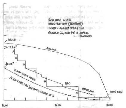
Jim, I am enclosing four plots, which I think you will find interesting. They show the required glass cloth width for spar caps by my calculation. The standard wing top and bottom are shown as well as the elongated 236-inch span. The upper smooth curve is the airload calculated by the Fourier series method described in "Theory of Flight" by Von Mises (Sec. IX.7). The lowest smooth curve shows the cloth width required using an average wing thickness of 15.8%. I averaged the wing thickness from 2 to 12 inches of chord at BL00. I got 4.26 inches thickness for a chord of 27 inches. I got the same result by working through the moment of inertia calculation in "Aircraft Structures" by Peery (pp. 416-418). So using 15.8% as the average spar thickness, I used a formula from Martin Hollman's book "Composite Aircraft Design" to calculate the tension in the bottom spar cap and the compression in the top spar cap. Then using 43000 PSI for compressive strength and 66000 PSI for tensile strength and .009 inches thickness, I calculated the glass cloth width of UNI required. The lower smooth curve shows the cloth width required versus butt line. The stair step shows the spar cap schedule specified by QAC.
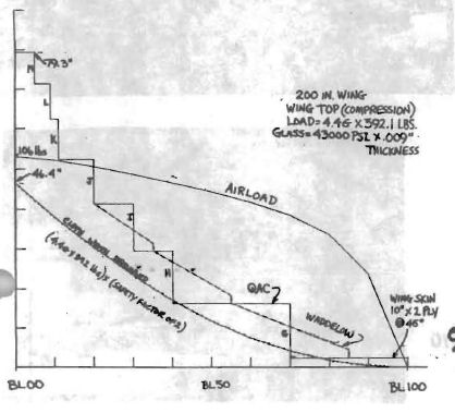
For the Wing Top, notice that at BL70, the end of spar cap "6", that there is not enough cloth width. (The stair step drops below the cloth width required curve.) So a standard Q2/Q200 wing should fail in compression at BL70 according to this calculation. Also BL40 just slightly dips below the required line. Either location would be the most likely failure point. Notice that the cloth width required line is for a 4.46 x 392.1 lb load with a safety factor of 2. Hence, the cloth width required line represents an ultimate failure load of 8.86 and a working load rating of 4.46.
Now look at the slant-step lines. These are the Waddelow tapered spar caps. Obviously they are a much better match to the cloth width required line. They never go below and are usually spaced uniformly above the required line. They are a much better spar cap schedule.
I allowed for only 10 inches of the wing skin as shown near BL100. There is more than that, but the remainder would not contribute a lot. Since the wing skin is at 45 degrees (two layers) it has a low (8500 PSI) strength. This 20 inches is equivalent to only 2.3 to 2.6 inches of 0 degree oriented UNI.
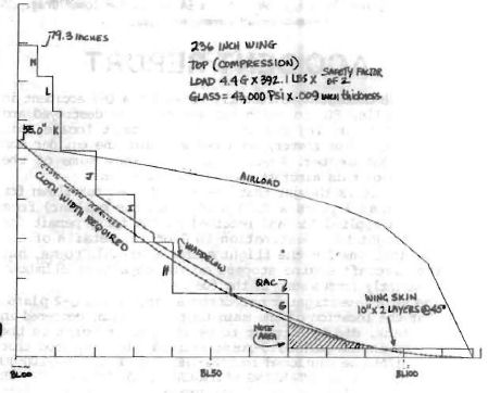
The second two plots show longer wings of 236-inch span. If the builder did not lengthen the spar caps, the wing is weak at BL85 even with Waddelow spar caps. A standard QAC wing is well below the cloth width required line. Obviously people building longer wings should use the Waddelow schedule but extend the "6" lamination to about BL95.
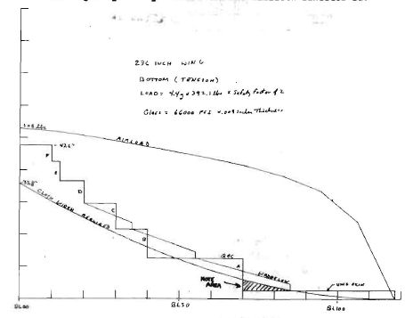
I think I would extend all of the spar caps a few inches. Keep in mind that your layups may be of different strength. They could be weaker or stronger than the 43000 PSI compressive and 66000 PSI tensile strengths used for these calculations.
On another question I have been trying to calculate the best canard angle. I still have some work to do to get a good number here. If you ignore engine thrust and elevator slot leakage, I get about 1 degree (per QAC plans). Adding in engine thrust seems to change that to about 2 degrees. So far I haven't been able to figure the slot leakage. I used an airfoil panel program to get the lift line slope and moment for the Eppler 1212R wing airfoil since I don't have measured data for it.
As a parting thought, I am considering using a different airfoil for the wing. Probably a 64 series for lower drag.
You can order a PDF or printed copy of Q-talk #19 by using the Q-talk Back Issue Order Page.