QUICKIE NEWSLETTER 12 page 3


- Details
- Category: QAC Newsletters
- Published: Monday, 13 November 2006 09:11
- Written by Quickie Aircraft Corporation
- Hits: 2182
|
 |
|
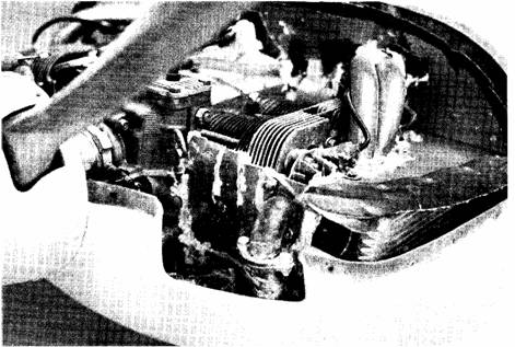
| Closeup view of the Revmaster 2100-DQ engine installed in the Q2. | ||
| NUMBER: Q2BT5 DATE: 18 FEB 1981 Page 11-4; Canard shear web pulley mounts; The positioning of the pulley mounts shown in the Q2 Construction Plans may need to be altered for individual installation interferences and fit. Consider the elevator pitch control system and previous routing of the brake line conduit out to the wheel pant prior to installing pulley mounts. You should strive for the straightest routing possible. NUMBER: Q2BT6 DATE: 18 FEB 1981 Page 10-2: Offset dimensions given in illustration may be altered up to 0.15” to provide straight cores l’rom BL15 to BL100. Do not accept kinks in leading, trailing, or top and bottom edges. NUMBER: Q2BT7 DATE: 21 FEB 1981 Page 14-2; Rudder Installation; For ease of installation, the top of the rudder and the bottom of the vertical fin trailing edge foam core should be trimmed to be perpendicular to the vertical fin core. NUMBER: Q2BT8 DATE: 28 FEB 1981 Chapter 11; The wheel pants are sized for optional 500 x 5 aircraft tires in place of the standard tires. If you decide to utilize the standard tires, the wheel pants can he made smaller, lighter, and more efficient. To do this, use urethane foam scraps as corner blocking inside the wheel well area to allow larger radius corners when carving. Pictures that you have seen of Quickie Aircraft Corporation’s Q2 represent these smaller wheel pants unless specifically called out otherwise. |
02 PLANS CHANGE NOTICES Q2 Plans Change notices (Q2PC) are mandatory revisions to the Q2 plans. Each Q2PC has a number and a publication date along with a description of the change. All Q2PC notices should he incorporated into the builder’s set of Q2 Construction Plans immediately upon receipt by the builder. Any questions on a Q2PC notice should be referred to Quickie Aircraft Corp. NUMBER: Q2PC1 DATE: 6 FEB 1981 Page 8-5; An easy change will increase the shoulder room in your Q2 by as much as 0.75”. Instead of making each longeron flush with the inside skin of the fuselage shell, remove the inside skin and foam core, and locate the longeron flush with the outside skin of the fuselage shell. Use the same lamination schedule as the Q2 Construction Plans call out. This change will also improve the canopy hinge geometry. In addition, all Q2 kits have been shipped with 3/4” x 3/4’ longerons instead of the 5/8” x 5/8” longerons indicated in the Q2 Construction Plans. NUMBER: Q2PC2 DATE: 21 FEB 1981 Page 5-1; Main Wing, BL50-BL100 Lt and Rt sketch; The sketch contained within the Q2 Construction Plans is in error. In order to hot-wire both a right and a left BL50-BL100 main wing core, it is necessary to place one set of Templates 2 and 3 upside down from what is shown. Otherwise, you will have two BL50-BL100 Right main ving cores. |
|