Q-talk 83 - LETTERS

- Details
- Category: Q-Talk Articles
- Published: Thursday, 31 August 2000 07:11
- Written by Tom Moore
- Hits: 3308
Tom,
BRAKING MODS
As some of you know, I have installed toe brakes on my Q200. After two years and about 200 hours of experience which includes three versions of the wheel caliper installation and four different toe pedal ratios, I have finally brought the brakes along to the point where I am satisfied with them.
My feeling from the beginning is that a taildragger NEEDS differential brakes. All other taildraggers have them and the reason is that they are the most powerful steering mechanism available, and taildraggers need effective steering. I chose toe brakes rather than hand differential brakes because I had about 600 hours in taildraggers and that is what I was used to and I wasn't about to give them up.
I originally installed the Airheart brake calipers per plans, but they proved to be somewhat erratic. I believe it was because the original design of the caliper mount was not well done. The support, which is supposed to provide for floating of the caliper, in fact can bind because of the off center force from the rotor. After some taxi testing, I decided to solidly mount the caliper and float the rotor instead. This was somewhat better, but still not as smooth as I wanted. So upon the recommendation of one of us (Thanks! Sam Hoskins), I converted over to the modification worked out by Bob LaRue and published in the Sept/Oct '89 Q-TALK Newsletter. This proved to be a worthwhile change because it smoothed out the action of the brakes very nicely.
Since I had been warned that the wide stance of the Q would make the differential brakes touchy to steer with, I reasoned that the brakes should not be too powerful. With that in mind, I deliberately desensitized the brakes by using a mechanical disadvantage in the toe pedal lever ratio. My first toe brake pedals were set with a ratio of pedal height to master cylinder lever length of 1:1.5. I learned to steer and brake with this, but the brakes were too weak to be much good. So I remade the pedals with a ratio of 1:1. This was better, but still not powerful enough. Interestingly, the airplane was NOT harder to steer with the more powerful brakes. I flew the Q with this setup, but was having a hard time stopping the airplane in less than 3000 feet or so. So at the first annual, I changed the ratio to 2:1. Now I was beginning to get reasonable braking. And again, the airplane got easier to steer straight under heavy braking. Another change at this year's annual brought the ratio to 3:1. Now the brakes feel like proper brakes and heavy braking is possible. Each time I have made the brakes more powerful, the plane has gotten easier to steer. This seems counter intuitive but I think the reason is that there is far more "touch" now. That is, I don't have to mash down so hard on the pedals to get effective brakes.
So the brakes consist of: Original Airheart calipers with hard linings. LaRue modified caliper mounts. Matco master cylinders with remote reservoir. And 3:1 ratio toe pedals mounted on top of the original rudder pedals. This arrangement is a keeper.
Bob Farnam, Livermore, CA
This email address is being protected from spambots. You need JavaScript enabled to view it.
Hi Tom,
Things are getting close on my Tri-Q2. The wing, canard, canopy and fuselage are all primed now. I'm doing some minor spot filling here and there and getting the control surfaces ready for prime now. I'm also about halfway through wiring the instrument panel. I'm using .062 Molex power connectors to make the instrument panel removable. That's working out well so far.
I'd like to show how I made my belly board actuator for my Tri-Q2. It is not flying yet, but I expect to be ready in the next few months. There may be others who are trying to work out the same issues and this might stimulate some ideas.
The Tri-Q per-plans actuator for the belly board mounts to the master brake cylinder phenolic attach point in the left console. An aluminum tube extends about 4 inches above the top of the left console and uses an elongated version of the original brake slot to control the belly flap. I've placed my throttle, mixture and carb heat in the lower left side panel just above the left console. The per plans belly board actuator was going to congest the area even more so another location or method was needed.
I had a fairly short vernier that I thought I could mount in the center console with the knob pointing forward and up at a slight angle to deploy the belly board. After some thought about this arrangement and how to implement it, I realized it might be a poor design in a go-around. I confirmed that with Bob Malechek who agreed that the belly flap does take significant force to retract in flight. The vernier has very little mechanical advantage used this way so it was clear I needed to go back to some type of lever to gain a mechanical advantage and a margin of safety.
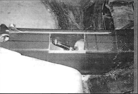
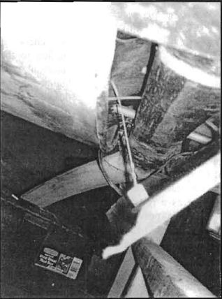
After seeing the type of center console mounted actuator you and Bob Malechek have in your QAC plans belly boards, I liked that location and how the length of the center console could be used to absorb a lever. You have a captured aluminum arm with a pivot point just under the surface of the center console that, when deployed, releases a cable forward toward the belly board mounted under the fuselage in the area of the canard/main gas tank region. I liked the installation because when the belly flap was not deployed only the captured end of the lever sticks up in the cabin a little bit and is out of the way for the most part.
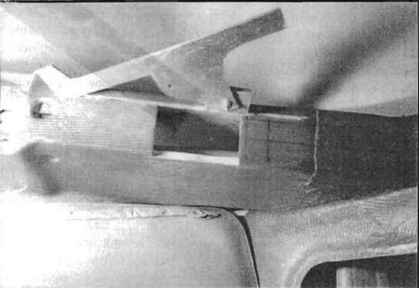
The belly board on the Tri-Q is located further aft in the area between the main gear legs where the bottom of the fuselage was cut out to install the main gear bow. That means to deploy the QAC belly board the actuator releases the cable forward while the Tri-Q belly board requires an aft cable release. I wanted to keep the installation as simple as possible so I eliminated solutions that would require a pulley to help reverse the direction of the cable release. It was apparent that the pivot point for a Tri-Q belly board release similar to the QAC version would have to use a pivot point some distance below the top of the center console to get the desired cable release. I determined that the per-plans Tri-Q actuator had a throw of about 3-1/2 to 4 inches. On paper, I figured out the radius from a pivot point that would move a point at the other end of the radius 3-1/2 to 4 inches when rotated through a 90-degree arc. That radius, plus the room needed to attached a Nicopress cable and allow it to move freely under the top of the center console, gave me the length from the pivot point up to the top surface of the center console. The design started out looking like a capital L with the top of the center console to the pivot point being the short leg. The length of the other arm was another thing altogether. Since the pivot point was down 4+ inches into the center console, the handle arm that is flush with the top of the center console in the retracted position or the longer part of the capital L would be aft of the point directly above the pivot point when the belly board was deployed. To visualize this, if you place a piece of paper on a table that is cut in the shape of a capital L where the long leg is horizontal and the short leg is point down, you would have the basic arrangement. In the QAC setup, the pivot point is very close to the intersection point between the long and short legs of the letter. In my design, the pivot point is down toward the bottom of the short arm. When you rotate the long arm 90 degrees aft while holding down the tip of the short leg, you see how the long leg handle goes aft of the pivot point equal to the length of the short arm. To account for this, I extended the handle aft past the pivot point about the same length of the short leg of the L. That way I wouldn't loose things down the slot aft of the pivot point when in the retracted position since the entire length of the slot is filled. Another benefit came as a result of adding this aft arm. When the actuator is in the deployed position, it will be experiencing the greatest pull on the cable due to the air forced against the belly board. To help this out, I installed a phenolic hard point for the aft leg to rest on when deployed. That way I don't have to worry about the actuator cutting a longer slot in the center console or poking through the seatback bulkhead. I set up the attach point for the pivot by floxing and glassing in a 2-1/2 x 2-1/2 x 3/8 inch phenolic block to the inside right surface of the center console. The cable back to the belly board presented a bit of a problem because it was going to be fairly short in the confined area and I wanted to be able to adjust the length. I ended up using a 10-32 post swaged to the end of a cable for the belly board side and a Nicopress eye on the actuator side. The swaged end apparently becomes as strong as the cable itself when attached in that way.
There is one interesting thing about belly boards I've notice over the years. When you ask flying Q pilots about them, you will hear everything from "I would never try to land without one" to "Don't waste your time adding a belly board." I've taken the attitude that it is far easier to add something like that now than it would be later after it is flying. Also each of these planes are unique and have their own flying characteristics as do the pilots with their equally unique flying experience and skills. I plan on letting this plane tell me if this is a good control for the way I fly.
Again, this is not a flying solution, so it is hard to recommend this to anyone. I hope it can generate some ideas, though.
Dave Richardson, Stow, OH
Tom,
In an effort to help share my building process with the QBA newsletter readers, I thought I would briefly mention some of the things that I have implemented on the aircraft. I think it is safe to say that most, if not all of these things, have been made as a result of multiple suggestions by other builders providing feedback through the newsletter and E-mail Q-LIST. I might first mention that before starting the project I ordered all back issues of the newsletter and created a Microsoft Access database that was used to chronicle all of the reader feedback that pertained my aircraft.
The articles were entered according to area (i.e. engine, avionics, airframe, etc.). By sorting the database I was easily able to see what people were having the biggest problems with. I then made sure to implement improvements in these areas. As I recall, there was one area mentioned quite often - fuel tank problems.
For the fuel tanks, I went ahead and built the fiberglass tanks but took extra effort to put down the extra layment and post cured to help avoid degradation and pin hole leaks. I then built access holes into both tanks for servicing later on if need be. The main tank access plate is on top, front and center of the tank just in front of the center armrest. It is rectangular and just large enough to fit my arm into the tank. The flange of the opening is 3/8" phenolic which was floxed in place after first removing the outside layer of fiberglass and foam. The flange is about 5/16" wide around the perimeter of the hole. Two plies BID were applied over the flange. The bottom side-mating surface of the flange had to be sanded and fitted to match the slight curvature of the tank at that point. The lid was 1/4" phenolic and mates over top of the flange held in place by 10 bolts with retaining nuts on the bottom (8/32). The lid is drilled and tapped to accept the fuel gauge sender, return line from header and fuel line. A similar type access hole was added to the header tank. Of course, 3/8" fuel lines were used throughout and a finger strainer tapped into the header. A 30 mm capacitive proximity sensor acting as a fuel level indicator is mounted 3/4" of the way up on the header and provides an alarm if fuel delivery from the main tank is not maintained. I believe that Kris Browne detailed a similar sensor technique in a previous newsletter. Leak checks of the tanks were performed with 1.5 PSI applied to the tanks through an air regulator and "balloon" type buffer. I would not recommend any higher pressures than this because the tanks are not designed for pressure in this manner. Of all things tried for detecting leaks, a slight soapy water mixture in a squirt bottle seemed to work the best. To my surprise, I found pinhole-leaks in the upper fuselage area of the header tank. After detection, I removed the access plate, painted pure wet epoxy in the area, screwed the plate back on and pressurized to force the epoxy into the pinholes. The leaks were gone.
*** TO BE CONTINUED ***
Lynn J. French, Broken Bow, NE
The remainder of Lynn's article will be in the next issue.
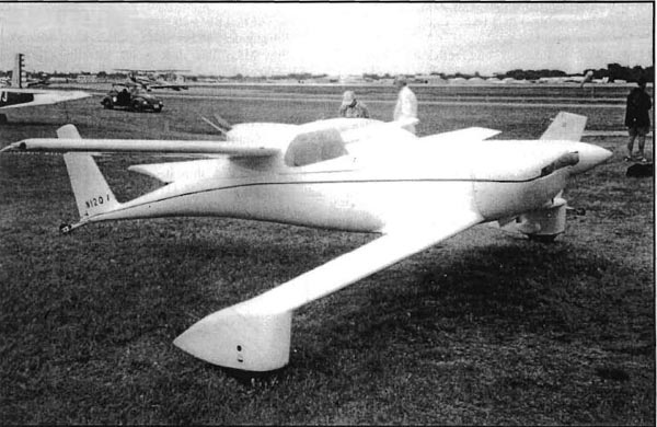
John Shryock of Kalispell, Montana at Oshkosh 1997
You can order a PDF or printed copy of Q-talk #83 by using the Q-talk Back Issue Order Page.