Tri-Q Wheel Covers / Fairings Installation
- Details
- Category: TriQ Plans
- Published: Tuesday, 28 December 2010 16:30
- Written by Scott Swing
- Hits: 5420
Wheel covers and gear to fuselage fairings should be installedprior to finishing of main gear. This is to miniminze scratching andto provide a "dam" for some bondo work.
The main gear fairing is installed by sliding the fairing tightlyinto place and drilling two attach holes through the fairing and intothe fuselage on the bottom of the aircraft. These holes should besmall enough for the AN 631 phillips flat head screws. Enlarge thefairing holes enough for clearence and use the A3135-017-24A countersunkwashers.
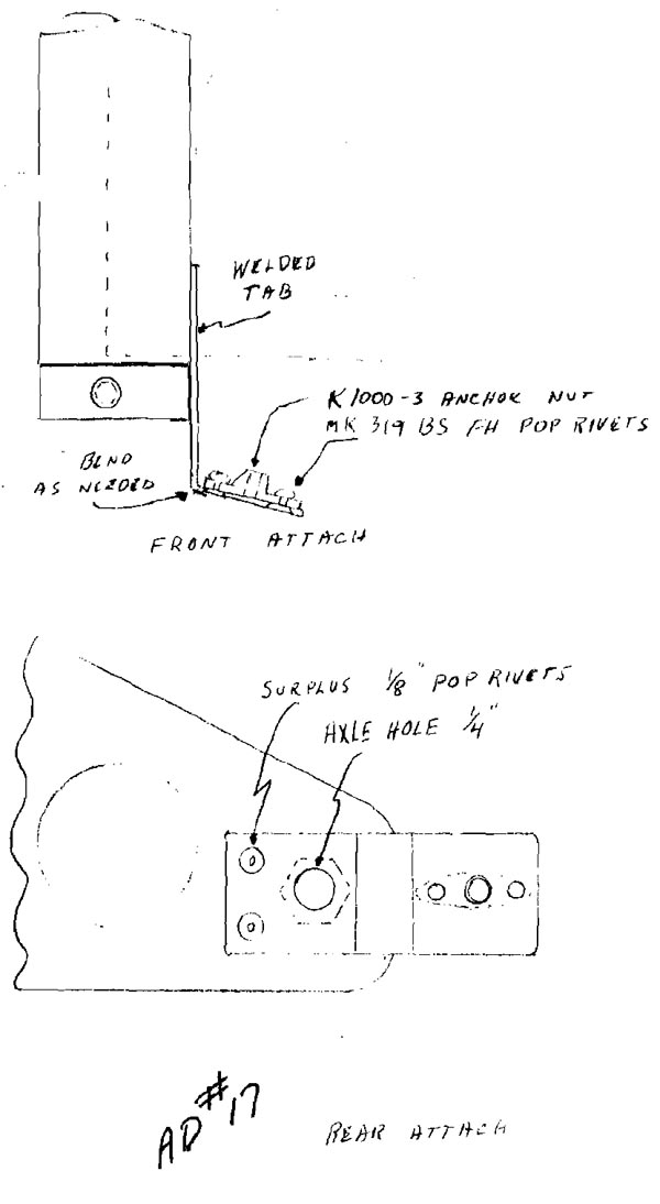
The wheel fairings are attached in a 3 point fashion. Fabricatetwo strips of the 1" wide 4130 flat steel as illustrated. Zincchromate when finished.

position and attach to the lower two axle bolts. Final shapingwill be necessary to insure proper fit. This is best done with thefairings assembled and positioned over the tires. Allow at least 3/4"clearence between tires and covers by setting a spacer block on topof the tire during fitting. Make sure covers are aligned fore andaft with the wheels and with the proper camber.
When the brackets are properly aligned, position a pen lightbehind the anchor nuts and mark and drill the holes. Lock in placeusing the MS24694-549 10-32 countersunk machine screws and the A3235-02B-935 countersunk washers.
The outboard attach is made by inserting the 5/8" x 3" aluminumplug into the axle with the threaded portion the outside. Applya small amount of bondo to the plug where it enters the axle andslide the plug out until it is firmly against the wheel cover.Using a pen light, carefully mark the position of the 1/4" hole.Remove the wheel covers being careful not to break the bondo holdingthe 5/8" rod to the axle.
Scribe a mark on the 5/8" rod through the hole used for thecotter key in the axle nut. Once this is done the 5/8" rod can beremoved and the cotter key hole drilled through the 5/8" rod. Youcan also drill the 1/4" hole in the wheel cover and attach a 3/8"washer to the inside of the cover directly over the 1/4" hole. Aone bid patch will hold the washer in place. After cure, countersinkthe hole for the 1/4 x 20 x 3/4" FU machine screw and A3475-020-24Acountersink washer.
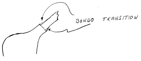
The wheel covers can now be installed and a bondo transitionbetween the covers and gear legs can be made.

The gear legs are now ready for final finish work.
The nose gear fairings consist of the two wheel half covers andthe strut fairing.
Fabricate the attach brackets from the one inch 4130 steel asillustrated.


Fit the wheel cover halves together over the nose wheel forkand adjust the front and rear bracket, for a snug fit to the fairings.Shine a pen light from the back side of the anchor nUts and markthe hole locations. Remove fairings, drill holes and attach usingthe MS24694-549 10-32 countersunk machine screws and A3235-028-935countersunk washers.
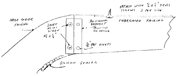
The strut fairing is attached using an aluminum clip at thebottom and screws at the top.
See illustration:
![]()
The fairing covering the gear from the firewall aft, will haveto be fabricated using scrap foam glued to thesteel gear and shapedto fit. Variation in the method used to close off the bottom skinon the Q2 would not allow us to pre fab this fairing. Once thisfairing is properly shaped to fit the area, and matches the airfoilshape of the supplied gear fairing, cover over the foam, extendingminimum of 3" on all sides, with duct tape. Glass over duct tapewith 2 layers of bid and let cure. After cure, remove and trim sothere is at least a 1/2" lip to attach to fuselage.Pop rivet a 1" alurnimum flange to the forward opening to beused as the rear attach for the gear fairing.

After painting, the nose gear fairing can be attached permanentlyby using clear or white silicone cement along the trailing edge andfirmly holding together with duct tape until cured.


