Q2 Plans Chapter 16 Page 16-06

- Details
- Category: Q-2/Q-200 Plans
- Published: Friday, 05 May 2006 20:05
- Written by Quickie Aircraft Corporation
- Hits: 3384
|
ENGINE BAFFLING
..... The purpose of the engine baffling is to provide adequate airflow for cooling to all critical areas of the engine and accessories. Air enters through the cowling air inlets located on either,side of the spinner. A vertical baffle located in front of the forWard engine cylinders forces the incoming air to travel upward across the cylinders and then down through the fins, exiting the bottom of the cowling through the variable opening cowl flap. Another vertical baffle located just aft of the rear cylinders assists in forcing the air down through the cylinder fins. Likewise, baffling between the cylinders and the sides of the cowling performs the same function. An opening in the forward vertical baffle allows airflow into the oil cooler. Once having passed through the oil cooler, this air mixes with the spent cylinder fin air to exit through the cowl flap. .....Aluminum with an 0.032" thickness is the primary baffle material. Approximate full size patterns are provided. However, there is no easy way to fit baffling around the complex shape of the engine. Areas of leakage must be closed off with aluminum in the case of large holes, and silicone in the case of small leaks. The black rubber asbestos is used between the aluminum and the cowling to provide a close fit when the cowling is installed. Pop rivets (BSP42) are used to join the pieces of baffling and asbestos together. Small angles can be bent up from the 0.03211 thick aluminum to attach the baffles to bolts on the engine painted red. In this manner, the baffling will be removable. .....Baffling can easily consume 10 manhours of work, so don't hurry. Inadequate cooling is a major factor in many homebuilt aircraft engine problems. 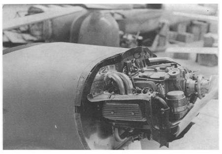 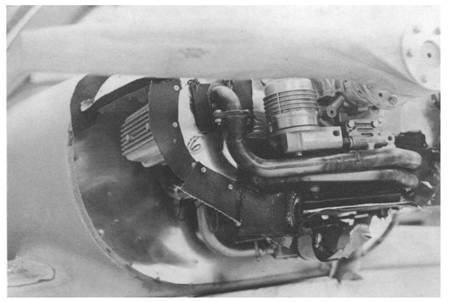 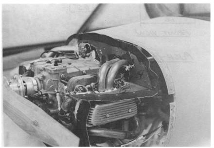 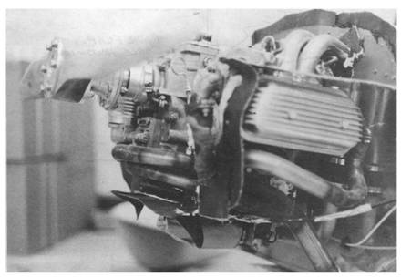 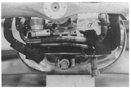 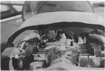 |
||||
|
||||
PAGE
16-5 |
||||