Q2 Plans Chapter 17 Page 17-02
- Details
- Category: Q-2/Q-200 Plans
- Published: Thursday, 04 May 2006 20:05
- Written by Quickie Aircraft Corporation
- Hits: 3546
   HEADER TANK PLUMBING
..... Prior to permanent installation inside the fuselage, the plumbing for the header tank should be installed. The accompanying drawing shows the location for all header tank plumbing. The fuel feed to the engine should be patterned after the main fuel tank feed shown on Page 14-3, including the screen and flox, but omit¬ting the drain valve. Both the feed line from the main fuel tank and the feed line from the engine should be made from 1/4" 0.0. Aluminum tubing. Allow the tubing to extend out from the header tank about 6 inches. Use liberal amounts of flox to seal the exit points. .....The fuel overflow return tube is made from 5/8" 0.0. Aluminum tubing. It should extend to near the very top of the aft part of the header tank, in order to maximize the fuel capacity. Permit it to extend about 6 inches below the header tank, and seal the exit point with flox. .....The routing shown for the plumbing is nominal, but will avoid interference. 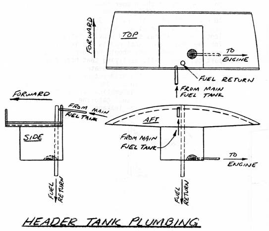 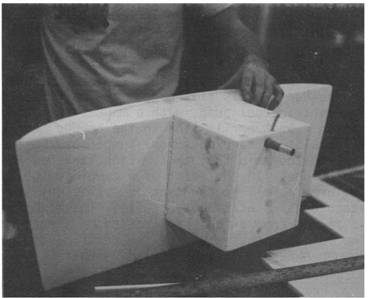 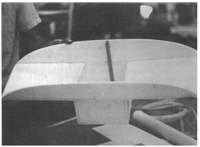 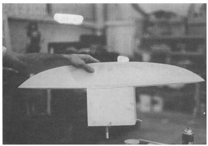 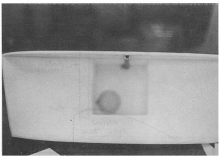 |
||||
|
||||
PAGE
17-2 |
||||


