Q2 Plans Chapter 14 Page 14-01


- Details
- Category: Q-2/Q-200 Plans
- Published: Wednesday, 17 May 2006 15:05
- Written by Quickie Aircraft Corporation
- Hits: 5412
|
FUSELAGE DETAIL ASSEMBLY WRAPPING THE TAILSPRING
..... The tailspring provided is a molded S-Glass roving tailspring with extremely good bending strength along the length. Because of the production method, however, the tailspring does not yet have sufficient strength torsionally, to provent torquing up in a tight taxi turn. .....To provide this torsional strength you must wrap a piece of BID at 45 degrees to the length of the tail¬spring, around the tailspring until you obtain 3 layers of the BID. Needless to say, you will prepare the tailspring by sanding the surface. Pure epoxy is used for the lamination. MOUNTING THE VERTICAL FIN
..... .....The vertical fin is mounted to the fuselage only after the rear fuselage shells are bonded together. .....The vertical fin sets down into the fuselage with the vertical fin root end resting against the bottom of the fuselage. This necessitates considerable trim¬ ming of the top fuselage to permit the vertical fin to drop down through. Also, the nose of the vertical fin below the top fuselage is trimmed back so that the vertical fin will rest flush against the bulkhead. Trim slowly so as to avoid making a bigger hole than necessary. The general arrangement drawing included here gives the mounting arrangement. The vertical fin slot is located approximately 5" forward of the tail of the fuselage, so that the nose of the vertical fin can fit snugly against that bulkhead. .....Use a plumb bob hanging from the trailing edge of the top of the vertical fin, with the fuselage levelled laterally, to verify that the vertical fin is positioned vertically. Your eyeball from a distance is used for a second check. .....When the vertical fin fits into the fuselage properly, you are then ready to prepare for mounting the tailspring. The core foam on the vertical fin is hollowed out as shown, so that the tailspring can sli.de forward from the aft end of the fuselage. The aft fuselage may have to be trimmed forward until the width is 0.75" MIN, which is needed for the tailspring to slip through. The bottom fuselage can be slotted as shown to insert the tailspring. Do not worry about removing excess foam as you tunnel through the vertical fin core. It is necessary to have a minimum of 0.8" of space in all directions around the tailspring in preparation for mounting. Allowapprox¬ imately 9" of tail spring length to protrude aft of the end of the fuselage. .....The vertical fin core foam is not dense enough to withstand the tailspring loads. Therefore, when you are ready to insert the tailspring permanently into position, you will mix up a substantial quantity of flox to fill the hole first, so that when the tail¬spring is inserted, generous squeeze-out will result. Remember, at least 0.8" of flox must be around the tailspring to spread the loads. Note from the drawing that the flox completely fills the fuselage aft of the vertical fin. Before the flox has an opportunity to set up, verify that the tailspring will cure with its length parallel to the aft top fuselage line, and that it is not crooked laterally. 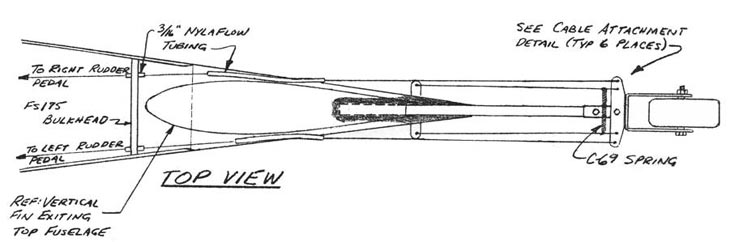 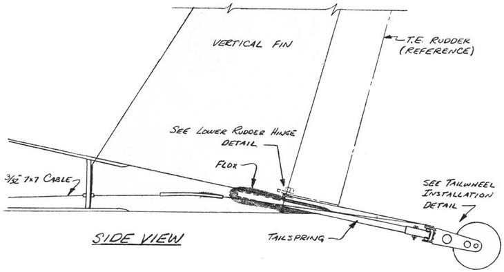 |
||||
|
||||
PAGE
14-1 |
||||