Q2 Plans Chapter 14 Page 14-02
- Details
- Category: Q-2/Q-200 Plans
- Published: Wednesday, 17 May 2006 15:05
- Written by Quickie Aircraft Corporation
- Hits: 3787
|
TAILWHEEL INSTALLATION
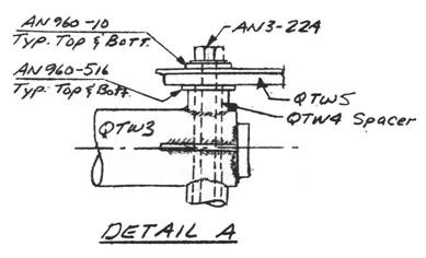
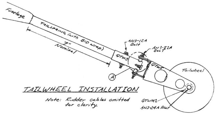
..... Once the tailspring has been installed in the fuselage permanently, then you are ready to install the tailwheel. .....Locate the following parts: QTW3, QTW4, QTW5, QTWMl, and the tailwheel. Insert the QTW4 spacer into the QTW3 weldment as shown. Trial fit QTW5 to the QTW3 assembly with a AN3-2LA bolt. It may be necessary to sand QTW3 in order to allow a small amount of vertical freeplay between QTW3 and QTW5. Once all the parts fit together smoothly, assemble as shown. .....Next, mount the tailwheel to the QTW5 fork as shown, using the QTWMI axle and AN3-24A bolt. .....The next task is to mount the entire tailwheel assembly to the tailspring. Start by leveling the fuselage laterally, and then trial fit QTW3 onto the end of the tailspring. Trim the tailspring if necessary to permit QTW3 to fit, or to obtain the nominal 7" length from the forward edge of QTW3 to the fuselage. Drill in the single AN3-12A bolt holding QTW3 to the tailspring after making sure that the vertical face of the tailwheel is indeed vertical. (Otherwise the tailwheel will wear unevenly). To mount the Tailwheel assembly permanently to the tailspring, mix up some flox and obtain good squeeze out of the flox upon assembly of QTW3 to the tailspring.   RUDDER INSTALLATION
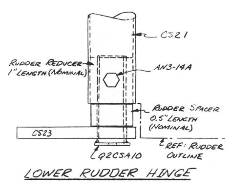
..... The rudder hinge assemblies are very similar to those of the ailerons, so review the section on mount¬ ing the ailerons before proceeding further. .....The upper rudder hinge consists of the CS22 plywood mount, which is bonded to the vertical fin core, and the same hardware and fittings called out in the Main Wing chapter section on 'Outboard Aileron Pivot Assembly', so follow those directions. .....The lower rudder hinge is detailed in the accomp¬anying sketch. The QCSMI material is used for a 1.0" length rudder reducer and a 0.5" length for a rudder spacer. The rudder reducer is pushed into the CS21 rudder torque tube. CS23 is the lower rudder phenolic bearing. CS23 is bonded to the vertical fin foam core with liberal quantities of flox generating good squeeze out. Q2CSAI0 is the rudder bellcrank, which is attached to CS21 with a AN3-14A bolt. .....Assembly is performed by trial and error fitting of the rudder, complete with all pivots, to the vertical fin until a satisfactory fit is obtained. The clearance on either side of the vertical fin slot should not be less than 0.06". The rudder should be trimmed top and bottom so that a minimum gap between the fuselage and rudder, and between the rudder top and vertical fin exists. When everything is ready, mix up flox and also some 5-MIN and jig the rudder into place and permit it to cure. Stirring sticks and some scrap lumber can be used to hold the rudder in position.  |
||||
|
||||
PAGE
14-2 |
||||


