Q2 Plans Chapter 14 Page 14-03


- Details
- Category: Q-2/Q-200 Plans
- Published: Wednesday, 17 May 2006 15:05
- Written by Quickie Aircraft Corporation
- Hits: 3284
RIGGING THE RUDDER/TAILWHEEL CABLE
..... The sketch on page 14-1 shows the cable layout to actuate the tailwheel and rudder. Note that from the rudder pedals, the 3/32" cable travels aft through 3/16" Nylaflow tubing fairleads at each bulkhead, exits the fuselage about 10" forward of the tail of the aircraft, and then goes directly to the tailwheel weldment, QTW5, where it is attached to the outboard hole using a thimble and nicopress sleeve attachment. The inboard holes on QTW5 are used to attach cable (using the same type of attachment) that runs forward to Q2CSA10, the rudder bellcrank, where the cable is attached with another thimble and nicopress sleeve arrangement. The left and right sides are mirror images. The C-69 spring is used between the cables traveling to the rudder, to provide tension on the cables at all times. .....Cable attachments should be accomplished with no weight on the tailwheel, and with the rudder and tailwheel in the neutral position. (Use the rudder rigging template.) It is recommended that the QTW5-Q2CSA10 hookup be accompished first. Those cables must be as tight as practical. Then, hookup the rudder cables to the outboard holes of QTW5. Since there will be a quick disconnect later at the fuselage cut point, just cut enough cable to reach the fuselage cut point. The stop on QTW5 may need to be modified by filing it back in order to reach the limits of rudder travel indicated on the rudder rigging template. RIGGING THE RUDDER PEDAL CABLE
..... The 3/32" cable is attached to the rudder pedal using a cable shackle, thimble and nicopress sleeve, as shown. You may wish to wait until after the quick disconnect fittings are assembled at the fuse¬lage cut point, in order to better set up the angle of the rudder pedals. 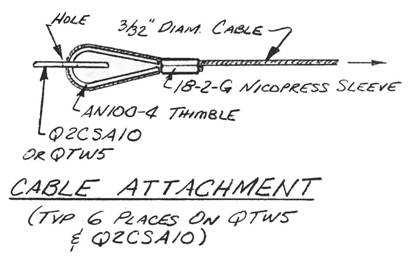 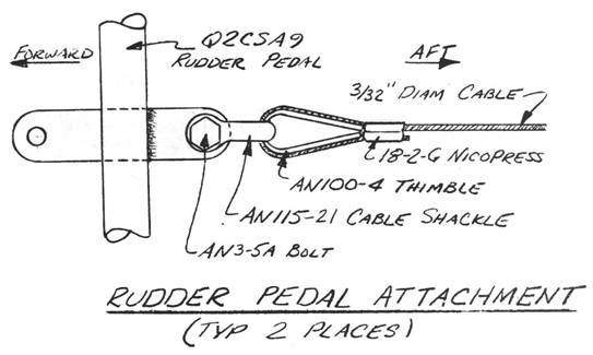 MAIN FUEL TANK INSTALLATION
..... Once installed, the main fuel tank also serves as a support for the legs of the pilot and passenger. The geometry of the tank was, therefore, laid out to provide not only fuel volume, but also adequate support. .....A fuel drain valve must first be installed in the bottom fuselage at the approximate low point of the fuel as part of the normal preflight checklist. .....Begin by locating FS45 at BLOO. Draw a 2" diameter circle around that point and contour a depression in the center of the circle that is 111 square and results in a foam thickness of 1/4". A toothpick is useful for gauging depth. Make a smooth transition around the area. .....Bond in with Flox the 1" x 1" X 1/4" mild steel plate and then laminate 2 BID over the entire depression overlapping a minimum of 1" onto the inside bottom fuselage skin. Once that lamination has cured, make a 'dome' from some aluminum screen door screen that covers about a 2.5" diameter circle, and attach the dome to the bottom fuselage over the depression with flox all around the perimeter. .....From underneath the fuselage, tap a 1/8" NPT hole into the mild steel plate for the fuel drain valve, which then may be inserted and tightened. 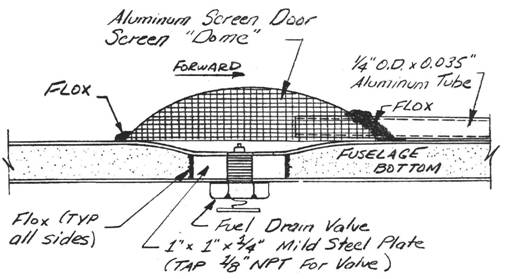 ..... Finally, find a piece of Versa tube Aluminum tubing of 1/4" O.D. and 20" in length and locate it as shown. The tubing pierces the aluminum screen and points forward, being afixed with liberal quantities of flox at the junction with the screen. Be careful not to flex the tubing unnecessarily to prevent fatigue of the tubing. .....The fuel tank must be trimmed to fit your fuselage. Refer back to the chapter on Basic Fuselage Assembly for a sketch showing the fuel tank positioning. The leading edge of the fuel tank is nominally at FS36.1; the trailing edge should be at about F558.1 in order to provide a nominal 6 inches of clearance between the fuel tank and the Seatback Bulkhead. You will find that the sides of the fuel tank need to be trimmed back to allow the fuel tank to sit down against the fuselage bottom. Verify that the elevator control rod C513 does not interfere with the top of the main fuel tank as it runs forward to the elevator by skipping ahead in this chapter. If it does, you must trim down the height of the main fuel tank to clear by a minimum of 3/8", or laminate a slot into the fuel tank for this CS13 clearance. .....Baffles are used to prevent excessive sloshing of the fuel within the tank, as well as to increase the stiffness of the fuel tank so that it may be stepped on during entry and exit from the aircraft. .....Three baffles are used; one spanwise baffle about 18" wide, and two longitudinal baffles that extend from the landing edge of the fuel tank to within 4 inches of the trailing edge of the fuel tank. The sketches illustrate positioning and size. Note that openings are left regularly along the baffles to allow fuel to move back and forth slowly. Particularly note the opening at the top which is part of the venting system. Those openings should be about 2 inches in length and about 1" in height, and need not be accurately shaped. .....The baffles are fitted using trial and error until they fit both against the fuel tank and also against the fuselage bottom when the tank is inserted into place. Each baffle should have 1 BID on each side, and the 1/4" thick white foam is used for the core material. Once each baffle is properly trimmed, it should be mounted permanently to the fuel tank with micro and a BID tape on either side with a minimum 1" lapping onto each surface. ,Upon installation of the fuel tank permanently to the fuselage, these baffles will be coated liberally with flox so that they bond to the fuselage bottom. |
||||
CONTINUED ON NEXT PAGE |
||||
PAGE
14-3 |
||||