Q2 Plans Chapter 16 Page 16-01
- Details
- Category: Q-2/Q-200 Plans
- Published: Friday, 05 May 2006 20:05
- Written by Quickie Aircraft Corporation
- Hits: 5422
|
ENGINE INSTALLATION ENGINE MOUNT INSTALLATION
.....Make 4 EM2 backup plates. A full size drawing is included. .....Find the 4 Q2EM1 engine mount'weldments. Use a AN6 bolt to stack each Q2EM1 to one EM2. Next, drill in 4 0.190â diameter holes in each Q2EM1/EM2 combination in the corners. .....Using the sketch entitled 'Engine Mount Holes', locate the four hole locations on the firewall and drill in 0.375â diameter pilot holes. 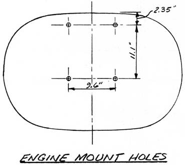 ..... Next, drill in the engine mounts on the firewall by taking each Q2EM1 and using an AN6 bolt to stack the Q2EM1 to the firewall, and then drilling the 4 0.19011 diameter holes per Q2EM1 through th_ firewall. Tempor¬airily mount the EM2 backup plate as shown using some AN3 bolts so that the engine may be temporarily mounted on the firewall. PRELIMINARY ENGINE MOUNTING
..... The purpose of this section is only to establish the size of the cutout in the firewall to clear the magneto and starter assemblies. Skip ahead to the section on âMagneto/Starter Boxâ to understand what the final shape and size must look like. Then, open up a hole in the firewall just large enough to clear everything. During the next section, you will make the final hole. Once the hole has been sized, remove the engine. 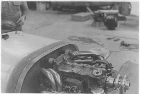 MAGNETO/STARTER BOX
..... On the Q2, the starter and magneto section of the engine projects aft of the firewall into a plywood box. This box is 9 sided and constructed from 1/8â thick plywood. It has the inside dimensions shown. These dimensions are rather critical, so follow them closely. Use a few dabs of 5-MIN to hold the 'jigsaw pieces' together and laminate 1 BID on both the inside and out¬side of the box. .....Enlarge the previous cutout in the firewall until the box will just fit through it. Attach the box permanently using 2 BID tapes on both sides of the firewall. Verify that the magneto/starter accessories will fit within the envelope of the box. 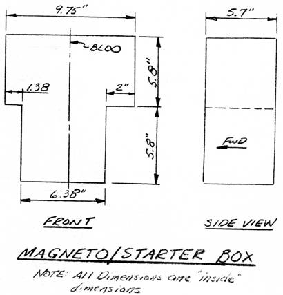 FIREWALL PROTECTION
..... Prior to mounting the engine permanently to the airframe, it is necessary to shield the firewall with fiberfrax and aluminum sheet. .....One layer of fiberfrax must shield all exposed plywood, including the inside of the magneto/starter box. To protect the fiberfrax from abrasion due to normal wear and tear, a thin sheet of aluminum is fastened over the fiberfrax. However, the aluminum sheet does not need to be placed over the fiberfrax protecting the magneto/starter box; you may choose to use 2 layers of fiberfrax wherever a sheet of aluminum is not used. .....The fiberfrax may be held in position with epoxy. It is fragile, so be careful not to destroy it in handling. To attach the aluminum to the firewall, use a few BSP46 rivets located not closer than 2" to the outboard edge of the firewall. (The cowling flanges will be mounted there later.) 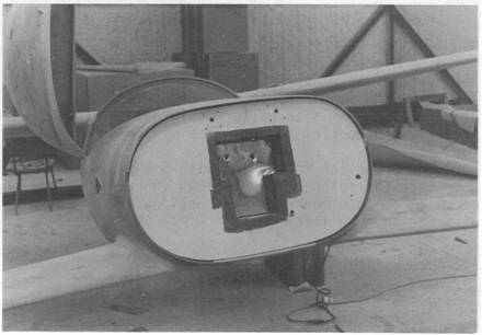 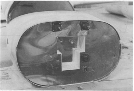 |
||||
|
||||
PAGE
16-1 |
||||


