Q-talk 119 - Things I Did Last Winter


- Details
- Category: Q-Talk Articles
- Published: Wednesday, 23 December 2009 16:24
- Written by Lynn French
- Hits: 4456
Tri-Q
1) Air conditioning problems:
Since completing my aircraft back in 2001, I have not been satisfied with the air conditioning. It was never very cold and it never had much flow. I quite often fly in temperatures near 100 degrees and have an engine cooling system that works well at those temperatures. However, the creature comfort within the cockpit has not been that good. Of course I am talking about the effectiveness of my NACA fresh air vents. I just couldn't get a good volume of air out of them. I put up with the problem for several years, but decided to take some action last winter. After studying several other aircraft that had good vent systems, I had realized that the root cause of my issues were 1) the vent openings were cut into the side of the fuselage too low and too far back and, 2) the vent style that I installed from Aircraft Spruce did not have the correct profile and was very inefficient. The only time I could get some air flow was up in level flight.
Of course moving the location of the vents or replacing them with a more efficient design, would mean cutting up the fuselage and a new paint job. Therefore, I tried a few simple things first to make attempts at improving the situation. I made sure that the canopy seal was intact, making sure there was not any excessive air leaking around the canopy that would counteract normal vent flow. Then I enlarged the shoulder strap seatbelt slots on the seat back bulkhead to allow more air to get through to the baggage compartment and out through the exit openings below the main wing. I then enlarged the exit vent openings themselves to ensure that this was not contributing to the problem. By doing these things the overall vent flow improved somewhat and I flew the aircraft for another summer.
However, I was not completely satisfied. I decided to try installing a better NACA vent in the existing location. My thought was that if I could remove the old vent and install a more correct and efficient vent in its place without damaging the exterior, I could possibly salvage the existing location and avoid any exterior painting. Determined it could be done, I set out to make it happen.
I decided to do the pilot side first since it was the worst of the two vents given the direction of propeller rotation and the shielding affect the canard has. Working from inside the fuselage, I cut and sanded out the old vent back to the outside skin. I had previously investigated the NACA profile and what makes up a proper vent. I then researched various sources for good vents. After talking to Charlie Johnson (aka OneSkyDog) about my problem, he asked me if I would like to buy a set of "proper" vents. He manufactures these things, and he claimed they were very effective. I took him up on a set of them as they looked to be made in such a way that I could install them from the inside of my fuselage. Van's aircraft also makes the NACA style vent that could also be installed from the inside. In either case, it was to my advantage because the existing vent opening would need to be enlarged.
With vents in hand, I carefully traced the cutout needed over the old vent opening. I shifted the trace as far up and as far forward as I could while still completely removing the old vent opening. I then cut and sanded the opening slightly smaller than needed. After painting the visible portion of the new vent, I prepared it to be glassed to the inside of the outer fuselage skin. I used some 5 min. epoxy and slight pressure against the vent to hold it into position while the micro and glass cured. Once secured, I carefully sanded the opening from the exterior to the final dimensions of the vent. This created a near seamless installation.
The good part is that the airflow is 10 times what I had previously. Airflow will still diminish significantly with high angles of attack, but it is now at a level I can tolerate. For those who are still building and have not yet located your vents, please take the time to look at others who have successful vents and be sure to get them high enough and forward enough to avoid the problem I had.
2) Rudder Trim:
It's kind of funny how one thing leads to another when it comes to working on these little birds. In this case I'm talking about the auxiliary fuel tank that I fabricated a couple years ago and my subsequent need for rudder trim. You see with all tanks full, my non-stop flight range can be over 4 hours. One of the problems for me with flights this long is the fact that my butt falls asleep from sitting in the same spot and not being able to move around much. I would shift my rear around, pull one leg back, or pull a knee up to help break up my posture, but I always had to keep a foot on one of the rudder pedals to keep the aircraft flying in trim. Some conditions would require slight right rudder, while others would require slight left rudder. If I could only pull both feet off the pedals it would open up some more options. So, while I had the aircraft torn down for several other mods, I decided to install a simple rudder trim mechanism that would allow me to take my feet off the rudder pedals. I wanted something simple yet lightweight. What I decided to do was remove the left side eye bolt that anchors the pedal tension spring to the firewall and replace it with a pulley. Pictures speak a thousand words here.
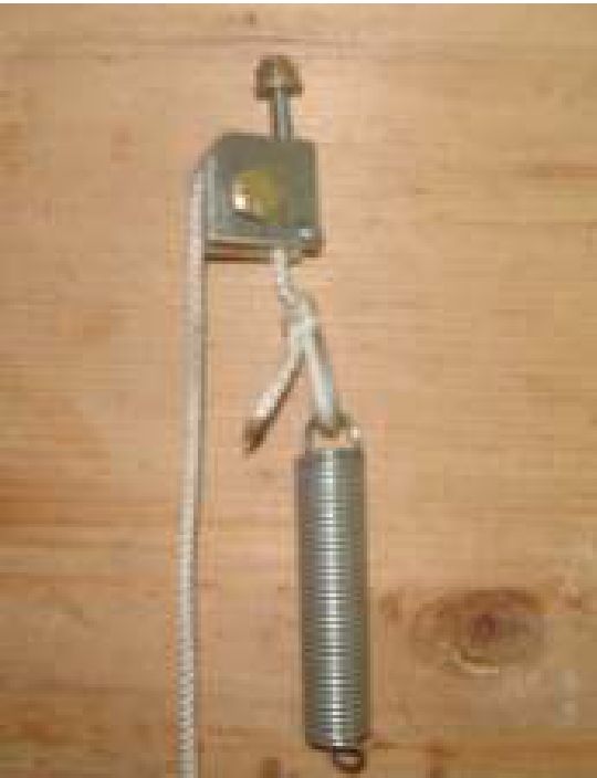
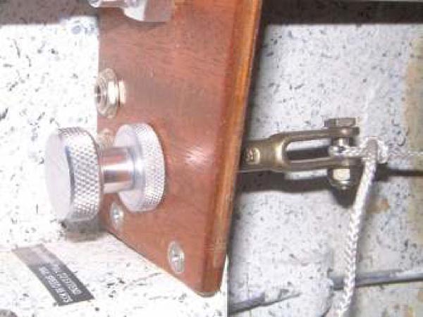
I then attached a cord to the tension spring, routed it back through the pulley and back up to my panel where I installed a simple threaded knob through the instrument panel.
It works similar to a vernier mixture control. Turning the knob one direction will tighten the cord, thus increasing the tension on the left spring causing it to overpower the right spring and therefore trimming the aircraft to the left. Likewise, turning the knob the other direction will loosen the cord causing the left tension spring to relax and let the right spring be dominate providing right trim. Works like a champ and doesn't weigh much. One should also add the inspection of the cord to their annual condition inspection.
3) Engine Upgrade:
No I didn't install high compression pistons on my O-200. I did install an Engine Control Unit which handles both ignition and fuel injection. I had been planning on installing electronic ignition to replace one of the magnetos and was nearly ready to buy one of the common units when my mind drifted briefly and I got totally carried away with a project way beyond a simple electronic ignition. What started out as an inquiry into fuel injection on the O-200 engine Q-list last fall, ended up being a full blown project to install an electronic engine control system last winter. After a few delays, the system was complete and flying by June.
Although there were several different electronic systems out there that have been installed on aircraft, they were automotive versions modified for aircraft engines. I found a small company that makes an Engine Control System designed from the ground up for aviation use. It has redundant control systems that allow backup if one system fails and a simple management system with the pilot/cockpit environment in mind. Unfortunately, this system has never been developed for use on an O-200. With an interested owner looking to expand his business opportunities, and an interested builder willing to engineer the system, we set out on a partnership to bring it to success.
The company is Real World Solutions and they now market this system to O-200 owners. This article is not intended to get into a lengthy discussion of all the activities it took to make it successful, but to give a high level overview of the installation and its benefits.
The most difficult software hurdle was developing the timing advance curve. After significant research and some reverse engineering of other systems, I plotted the RPM and Manifold curves to be embedded in the control chip.
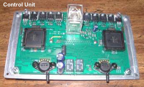
From a hardware perspective, the igniter coils, injectors, high pressure pump, fuel return loop, speed sensor and control unit had to be mounted. Although none of these items by themselves were extremely difficult, together they consumed a lot of time since I had to figure everything out myself. Finding someone to talk details about installing electronic fuel injection on an aircraft engine seems to be impossible.
I wanted to leave my existing MS carburetor installed as the alternative fuel supply system. I would also keep one magneto installed as backup. The carburetor would serve as the throttle body for the injection system, but it would also limit the true potential of fuel injection by virtue of the venturi restriction that would remain in place.
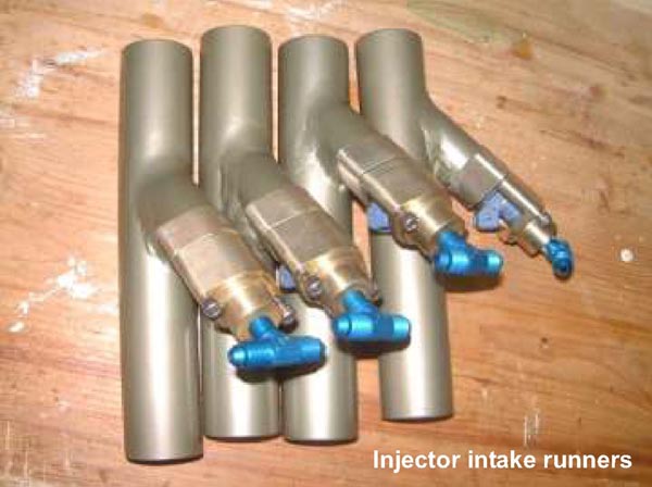
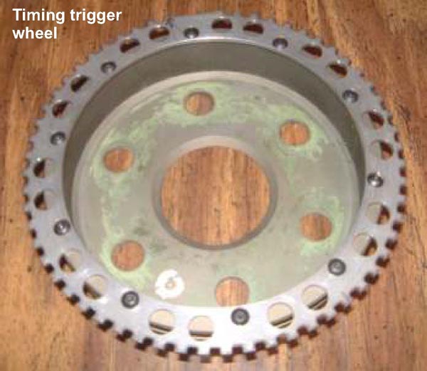
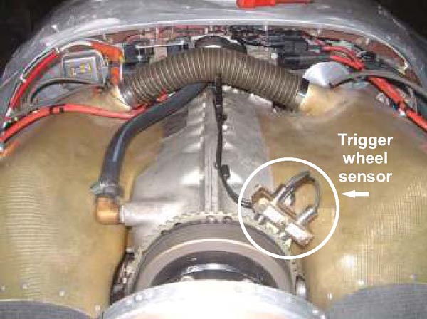
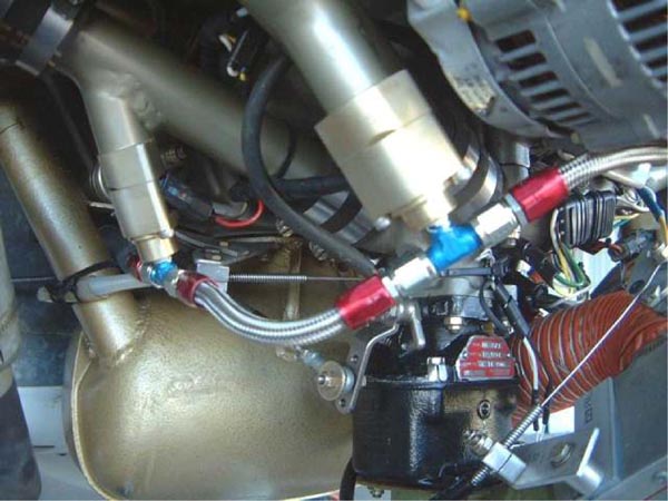
I built separate intake runners with injectors installed that simply replaced the stock runners. The high pressure pump and regulator were installed on the cockpit side of the firewall. Fuel plumbing modifications were made to allow return fuel into the header tank, and the igniter coils were mounted on the engine side of the firewall. I designed a custom speed sensor system which also includes redundancy to compliment the redundancy in the controller. The speed sensor timing trigger wheel ended up getting a little complicated because of my persistence to keep the existing front alternator pulley hub mounted on the prop flange.
With all systems installed, it was time to see what would happen. To my surprise, after setting for nearly 6 months, the engine immediately fired up and idled smoother than I could have ever imagined. I checked the timing at idle and it was right on target at 40 deg. of advance. Further testing at higher RPM's would reveal a problem with the RPM advance. After discussing the problem with RWS, they immediately corrected the issue and new chips were installed. Bingo! Now the RPM and manifold curves are right on target. After detailed checkout and full validation of the system I headed off into the sunrise. The performance changes were impressive and the higher I went, the more impressive it was. I'm not sure what the improvements are in terms of HP, but it varies by several factors including altitude and RPM. Immediately noticeable was the vastly improved fuel/air balance across all four cylinders as indicated by EGT's. When flying under carburetor control, the EGT's can vary between cylinders significantly depending on where the throttle plate is. This is a normal characteristic of any system set up like our O-200's. The problem with this is that you leave some HP on the table and burn more fuel getting it because of the inability to lean the engine to its peak performance. When I shut off the carb and turn on the injectors, the EGT's immediately balance to within 30 deg. of each other. Now all cylinders will lean to the same point and the control system always maintains the proper mixture level at all altitudes without any management from the pilot.
Regarding weight, I added about 9 lbs to the aircraft to accomplish both ignition and injection as described above. If one would decide to go full electronic and remove the remaining magneto and the carburetor (in lieu of a throttle body) the net weight difference would be closer to even. In addition, the installation of a throttle body would nearly eliminate the need for a carburetor heat system.
For those who might be interested in this conversion, I would be glad to discuss in more detail the challenges and benefits.
4) Standard automotive alternator conversion to external regulation:
As part of my engine control system installation, I upgraded portions of my electrical system. In addition to the circuits needed for electronic engine control, I added an essential buss to the panel and converted my alternator from internal to external regulation. As you may know, internal regulation is pretty much standard now days in the automotive world. Although internally regulated alternators are fairly reliable, they still have a failure mode that is not acceptable for use in aircraft. This failure mode occurs when the regulator fails internally and puts the alternator in full output mode irregardless of battery charge. This leads to over voltage and eventual battery failure - not good for electronics. What's worse, even if you were aware that the alternator was overcharging, you would not be able to shut it down by removing the field voltage via fuse, or breaker. The only recourse would be to turn off the master (provided you have the alternator wired into your system correctly), or have a separate breaker in your panel for the alternator output that can be turned off. So, it is usually recommended to install externally regulated alternators in aircraft. This not only eliminates the type of failure mode caused by internal regulators, but it also allows use of over voltage shutdown circuits that will interrupt the field voltage to the alternator and shut it down automatically before damage occurs. However, these off the shelf externally regulated alternators run about $500 from the popular aviation suppliers !
You can do the same thing with a little time using an $80 standard Denso alternator from your local parts store. Besides, whether the alternator costs $500 or $80, the bearings of either one will last the same amount of time and most likely be the first thing to go. Since I am not a technical writer I will cop out on this one and reference you to my web site for a better description of the conversion process with photos. Check it out at:
http://www.carrollsweb.com/ljfrench/The%20Airpl ane/Alternator%20Conversion/alternatorconversi onpublish.html .
As I mention on my web page, the original thought for this process was provided in a back issue of Contact Magazine. The only problem with the authors' concept is that it would not work on the 3 or 4 alternators that I investigated. The majority of Denso alternators use the same technique with regards to their regulators. What I outline on my web page, requires some modification to the alternator itself, but primarily it circumvents the internal regulator. A standard $18 external regulator from your local parts store is now mounted on the firewall to control the field of the alternator. A side benefit to this conversion is it allows you to choose from a broad array of alternator sizes and weights. The stock O-200 alternator weighs in at over 10 lbs. With this conversion I am using a mini, one wire alternator rated at 55 amps and weighs 5.6 lbs.
Geeesh! Don't you wish you were half as productive as Lynn was last winter?! Thanks for the great article Lynn.
You can order a printed copy of Q-talk #119 by using the Q-talk Back Issue Order Page.