Q-talk 103 - Ammeter Secrets


- Details
- Category: Q-Talk Articles
- Published: Wednesday, 23 December 2009 16:24
- Written by Dave Richardson
- Hits: 3000

Just what is an ammeter and what does it do for me in my plane? An ammeter is designed to measure the flow rate of electrons between a source of power, like a battery or an alternator and things that consume power, like radios and lights. An example of what an ammeter measures would be the amount of energy used by two different 12 volt lights; a landing light and an instrument panel light. It is easy see that the landing light would require more electrons to do its job than the instrument light, even though they are both 12 volt lights. The term for what we are talking about here is amperes. An ampere, or amp for short, is the measure of the number of electrons flowing past a given point in an electrical conductor in a given amount of time. One volt through a conductor with one ohm of resistance equals one ampere. Batteries are rated in amp-hours (Ah). For example, a rating of 17 Ah means the battery should provide one amp for 17 hours or 17 amps for one hour. Depending on how old your battery is or its condition, your mileage may vary. 50% of the rated Ah's is a good rule of thumb, if you're caught with a dead alternator.
The electrical subsystems in your plane can be classified by the number of amps they require per hour to run. This gives you a sense of how long your battery will sustain the electrical devices, if the alternator should fail. When you turn on the master switch without the engine running, plus some of the electrical devices like radios and lights, the power source is the battery. The batteiy will be depleted as it provides power to these devices. When the engine is running and the alternator is active, the alternator will be the main power source. If the total load of the devices used is greater than the amperage output of the alternator, then the batteiy will also help supply the devices with power. If fewer devices are turned on than the alternator is rated to handle, the surplus output from the alternator will be used to charge the batteiy as needed.
As you can see, there are quite a number of combinations in this process. The ammeter is a great tool that can help you determine what is happening with your amperes. Most ammeters found in airplanes have a scale that reads from a negative number on the left, to zero in the middle and a positive number on the right side, for example -30 0 +30 or -60 0 +60. When the needle points toward the negative number, the load exceeds the available alternator and battery amps. When the needle points toward the positive number, the alternator output exceeds the load and the batteiy is being charged. When the needle is centered, the loads are either balanced to the available output of the alternator and battery or the system is turned off. This one instrument provides a great deal of information.
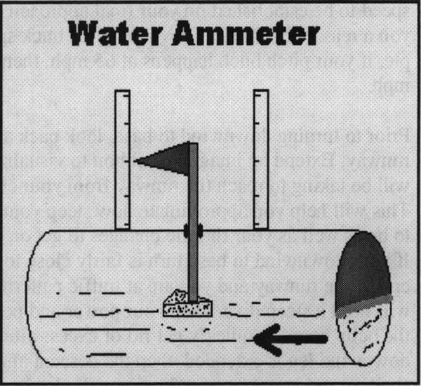
To help visualize what an ammeter does, imagine a piece of pipe that is in a system where water can flow in either direction and at different volumes. See the "Water Ammeter" image below. The triangular shape of the cork float will help the rod weathervane relative to the direction the water is flowing in the pipe. The pennant on the top of the rod will raise and lower relative to the volume of water flowing through the pipe. You can tell from this example that the ammeter needs to be in the thick of things relative to the push and pull of the alternator vs. the loads much like a rope in a tug-of-war.
Ammeters use a device called a shunt to measure the rate of the charge or discharge of the batteiy. A shunt is nothing more than a bar of metal of known resistance with large bolts on either end. The wire being measured is interrupted and all the current is sent through this bar. Two smaller wire connections near the large wire connections allow wires to be connected to the actual ammeter.
There are two different styles of ammeter / shunt combinations; Internal and External shunt ammeters. Internal shunt ammeters incorporate the bar of the shunt/resistor inside the ammeter housing. External shunts require an external bar as described above, in addition to the ammeter itself connected via a small pair of wires. External shunts are nice because they can be mounted on the firewall where the large wires you want to measure are easily accessible. Internally shunted ammeters require more heavy-gauge wire being routed to and from the ammeter on the instrument panel.
To be effective, the ammeter, or its shunt, needs to be positioned between the output of the alternator and batteiy. The load of all the devices needs to be in between those two items so it can sense the push and pull of the alternator and loads. There are three basic locations you can place the shunt.
1) Between the positive post of the battery and the hot side of the master contactor
2) Between the negative post of the battery and the primary engine ground
3) Between the switched side of the master contactor and the electrical bus
The first two locations have the disadvantage of sensing the large drains of engine cranking when engaging the starter. They also require the shunt and connecting wires to be large
enough to handle the significant amps being drawn by the starter. The ammeter and shunt must be capable of withstanding the loads being measured of the starter, too. It is easy for a starter to use more than 150-250 amps, so beware. The third option only monitors typical system loads. It does not measure the significant amps used by the starter. It can use smaller shunts and wires. Since veiy little of your time is spent cranking the starter, the amps drawn by the starter may be of little or no interest, unless there is a problem you are trying to troubleshoot.
The image below shows an example of how you can wire the internal ammeter that came in your kit. You can see how the energy can flow from the batteiy, through the master contactor, to the ammeter and then on to the bus where it is available to various load items. You can also see the path the energy can flow from the alternator, to the bus, to the ammeter, to the switched side of the master contactor and finally, to the batteiy. (For those purists out there, we are aware that the energy actually flows from the negative post of the batteiy through the load items, then back to the positive post of the batteiy but that's a little harder to describe given the space available.) You could also wire the ammeter to the hot side of the starter contactor, if that is more convenient. The charging will go back through the larger starter cable and back to the master contactor.
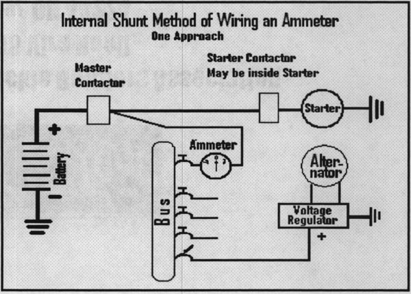
If you only see the needle pointing to the left on the ammeter, indicating a discharge, when you turn on the loads in your plane and no indication of charge from a functioning alternator, then you have some rewiring to do. You will find that the path from the alternator output, back to the battery does not go through the ammeter. A good rule of thumb for an internally shunted ammeter is:
? Wire the + post of the batteiy (or switched side of the master contactor) to the + terminal on the ammeter.
? Wire the - terminal of the ammeter to the bus.
? Wire the + output of the alternator to the bus.
You can order a printed copy of Q-talk #103 by using the Q-talk Back Issue Order Page.