Q-talk 33 - LETTERS


- Details
- Category: Q-Talk Articles
- Published: Thursday, 30 April 1992 07:11
- Written by Tom Moore
- Hits: 2617
Dear Jim,
Sorry I'm late on renewal. I'll admit I was sinking with the preamble to the last newsletter. Glad, however, to see the "latest info" update.
My thanks to Tom Moore. I understand your position too, Jim. I have been so busy working on other people's projects, my own has been at a standstill the last four months or so.
Put those efforts into that Rotax and I know you'll be loving it. Thanks again for all the hard work, your supreme wit, and great sense of humor.
I'm working on the latest updated index. Got an order from Tom Collinge, "down under". Good to hear from the other side. I'll send you and Tom copies when complete.
Bill Archer
P.S. "Call Gene Sheehan" (Ed. Note: I have gotten the Onan yanked off my Quickie, so that's a start ...Then came the nice Sun 'N Fun interruption.) I'd rather mow the yard!
Dear Jim and Tom,
Here's my $20 for '92. Hope Jim makes swift progress in building and that Tom enjoys the work on Q-Talk.
Report for 1991 on N2AM our Q-200. It now has 350+ hours. Major trips include my visit to Springfield, attendance at the National Canard Aircraft Fly-In at Olathe, KS (with Mary), spent 3 weeks in the air touring the east slope of Rockies, Mt. Rushmore, Devil's Tower, and the Platte River Basin in Colorado and Nebraska during October. Over 30 hrs. air time and no trouble.
A follow-up fuel flow warning. You'll remember my problems in Springfield. This time coming back from Olathe we landed at downtown St. Louis, fuel was topped of, lunch consumed. We strapped in and taxied a short distance toward the active and then the engine quit. To shorten a long inspection process we found that the vent line running from header tank overflow pipe to an external ram air inlet just below canard on passenger side was full of fuel and required quite a hefty blow to force air thru the line and out the opened filler cap. Yes, I was careful to close the cap after.
On two later occasions the same thing happened. I've now installed a "T" in the vent line with a valve and second line (inside the cockpit) so I can easily confirm that the vent system is OK as part of my preflight. I don't like to think about what might have happened if I'd gotten another 2-3 minutes of engine run before fuel starvation occurred.
Art Jewett
Dear Jim,
I've done a little work on my Tri-Q200 this year. Most of it wasn't required by the designer but represents needed improvements. Although it is embarrassing to be the last one to fly, there is the mitigating advantage of benefiting from the experience of others.
This year's work included considerable effort to prevent water from entering the cockpit when the canopy is closed. It also included construction of a forward spinner bulkhead to diminish the risk of spinner cracking and installing of a rear fuselage bell crank to reduce loading on the rudder bearing.
Someday I'll finish the plane and fly it. I look forward to meeting my original objective of enjoying a fast cross-country machine. However, even if I never fly the thing, I'll still consider the effort to have been a success. I thoroughly enjoy the building process. Even when I'm not building, I often lull myself to sleep by trying to think through an impending building task.
Obviously, my enjoyment is much enhanced by sharing the experience of other builders, largely as a result of your efforts.
Yours truly,
Alfred H. Medley
Ed Note: Now this is the correct attitude. Some 10 years ago at Oshkosh the gray heads taught me, "If you wanna fly, go buy an airplane right now and fly. Only build a plane if you enjoy the process of creating something unique that also happens to fly."
Dear Jim,
After changing my aircraft goal from Q-2 to Q-200 and switching to the new canard, as well as changing from tail dragger with finished wheel pants to a Tri-Q200 with the anhedral eliminated, plus building a larger tank with a left-side stick capability (to handle the aircraft as I am accustomed), I am ready to finish old N49X, as is.
Having done the wheel pants and the instrument panel (not to mention spending most of the available weekends this autumn building a balcony on my house), the airfoil surface preparations are the present effort, in order to permit the fuselage/wing assembly next, with the final painting, engine installation, and detailing to follow.
1992 may yet be the year.
Sincerely,
Thomas L. Cline
Ed Note: Finally ... a very promising report, Tom.
Dear Jim,
With only 15 hours on our Q2, we are evaluating returning the Revmaster heads for valve and valve seat replacement. The plane has ground looped twice even though we changed the ground angle of attack from 9.5 to 8 degrees, so far without damage. Maybe this isn't enough. The as-per-plans brakes will be changed so they don't twist and bind. Otherwise we are pleased with the results. A 172, it isn't.
We sincerely hope you will continue producing Q-Talk. It is our only support line for a project that really needs it. Given the wealth of information and interesting reading your newsletters provide, I hope my next correspondence from you is the first issue for 1992, not a returned money order.
In any event, please know I appreciate the fantastic effort and your contribution to so many people for so long. Thanks!
Yours truly,
David J. Cyr
Ed Note: Thanks Dave. It's been an enjoyable team effort and I thank the rest of my team of writers who keep the info flowing in my direction in spite of all the other things they might be doing.
Dear James
I am still puttering away at my Q2 #16 (#2046). I have moved it to Foley, Alabama, where it rests next to my 337. I bought Scott Swing's Tri-Gear and have been struggling with it for nine months now. My fuselage is "Killing Me". The bottom right does not have the same curvature or shape as the left half. Very poor molds! The result is that the gear comes out of the fuselage differently on each side. Nothing else new except that the bird is here.
Sincerely,
Harvey Nack
Ed Note: The fuselage contour is a well-known problem (or should be by now). Persevere, it's not been a substantial problem.
Dear Jim
My apologies for leaving Dallas and dropping out of sight. I have not had time to do much of anything even though I am supposed to be retired! I have not forgotten you, the plane or the commitment to generate a newsletter index.
After I left Dallas, I was recalled by the company to go back overseas. I came back from Kuwait at the end of September and two weeks later was asked to work in training for a month. Another two weeks and that job will be done. Not many people get to retire from the same job three times in the same year!
The index is coming along, but time to work on it is hard to come by. I have the first two years finished and the current issue is input as it is received. Don't give up on me.
Gene Bowan
Ed Note: Knowing what a helluva job an index is, I will be an absolute model of patience. You will be on the QBA honor roll along with Archer.
Dear Jim
Statistics to date:
Model: Q-200 N202SH - S.N. 2614 - Total time: 537 hrs.
Question: Does anyone know where to get one of those nifty desk models of the Q2 that QAC used to make available to builders?
I have a Warnke prop that needs refinishing. Does anyone have any suggestions on how to go about this?
Sam Hoskins (618) 549-3302
Dear Jim,
This is a safety tip. The fuel transfer pump in my Tri-Q200 (N83HS) is a very reliable device. So reliable in fact the squeeze bulb with check valve was thought not to be necessary and was not installed. This kind of thinking is WRONG.
The need for the squeeze bulb to transfer fuel from the main tank to the header (a back up system) was driven home in a most dramatic way a few weeks ago.
Here is what happened. It seems that after having installed a new radio and Loran, I somehow placed a lot of strain on the hot lead wire to the electric transfer pump. On the first flight to check out the avionics, the fuel pump wire broke. A good preflight told me that everything was OK prior to departure. During the flight the pump-on indicator light came on when I switched the pump on. However, I was unaware that the pump was not working. Also, the header tank sight gauge was old and not very clear, thus making the fuel level hard to see unless the light was just right.
Needless to say I was surprised to find that even though the fuel pump switch is "ON" and the main fuel tank was full, I had only 3 gallons of gasoline remaining in the header tank ... and it was fast being consumed. I was about 10 miles from the airport so there was no real problem returning to base. There was about one gallon of fuel left in the header tank after I landed.
The broken wire was repaired with ease and, as you might guess, I now have installed a backup fuel pump -- the manual squeeze bulb. I bought a "coast guard" approved primer bulb at the local boat shop. Also the header tank sight tube was replaced with new clear plastic.
I recommend that all Q pilots check both pumps during pre-flight just to make sure they work. Also, replace the sight gauge with a new clear one once it starts to turn dark.
Bill Butler
Dear Jim
With all the things to do on the homestead it just seems like yesterday, well maybe last month, since I last worked on my Q-115 (115 H.P. that is!). I am just getting started on it again, still hope to be flying this spring. I have to finish painting the canard, make all the connections to the 0-235, reinstall the panel and fit the landing gear, about 250 hours work, I think.
Kimbull McAndrew, Alberta, CANADA
Ed Note: Thank Goodness! I thought we'd lost you in the wilderness, Kim.
Dear Jim,
Just a note to bring you up-to-date on my project, Q200 #2351. Work continues on a regular basis. As you may remember, I am working with Jim Ham, alternating workdays between the two airplanes. We have pretty much finished the airframes and are into systems installation and finishing now. The engine has been mounted, the cowling has been fitted, the instrument panel is built, (but not wired), and controls are all in now, including the rudder pedals and front fuselage cables. We are also working on mounting the firewall items. We expect to begin work on the baffling very soon. So far, the finishing has been limited to contouring the flight controls, which job is about done now. We have been using West System micro for the contouring. We are getting in eight to ten hours per week on the planes, so we are guessing at painting and final system work sometime around the end of this year.
Bob Farnam, Pleasanton, CA
Dear Jim,
I am currently in Dayton, Ohio for two months and the Tri-Q is at home needing new paint on the cowl and nose wheel pant.
I am including some pictures of the plane that were taken after we arrived home from Oshkosh. (Ed Note: See photo in Mar/Apr issue.) My son Terry and I took all of our camping gear and clothes for four days in the plane with the two of us. My weight is 170 lbs, Terry's is 152 lbs and we had 36 lbs of gear in the baggage compartment and four gallons of fuel in the aux. tank. Climb out was not spectacular but not a problem. We had a gross weight of 1174 lbs and could still cruise 152 mph.
Something I have been testing (not by choice) is flying in the rain. As you know our canard is the LS-1 airfoil with a homegrown carbon spar and elevators are 10% thicker than normal. The elevators were made thicker because my partner remembered an article by Jim Bede stating that this would reattach the laminar flow and make the elevators more effective. Here is what I have found. When I am at normal cruise (22 in. MP. and 155 mph) and I encounter rain my speed drops to 125 mph and will remain there until the wing dries. I get very little pitch change. The only thing that happens is that I slow down. I can watch the blunt trailing edge of the elevators where droplets form and until these dry up my speed is reduced. Anyone else notice this? It causes no real problem other than it costs more time and fuel to get from A to B.
While on the subject of rain, I bought some of the propeller leading edge guard tape that is advertised in the classified section of Sport Aviation and it works very well.
I have probably three or four hours of time in the rain and nearly 100 hours total time on the tape. It has stayed on and is undamaged to this point.
We are starting to get some Q drivers with hundreds of hours on their planes. John Groff and Sam Hoskins, I believe, have over 500 hours and I think I heard someone say they had 700+ and I have 310 hours and enjoyed every minute, well almost every minute, well at least the last 290 hours of it.
Any of you guys with confusers on Prodigy? Maybe we could converse via the Homelife/Outdoor Hobbies bulletin board.
Addendum to the above! I went home over the weekend and couldn't resist going for a ride, at 3000 ft and 20 miles from my home airport an exhaust valve broke. There was a loud noise followed by a considerable loss of power followed by constriction of the sphincter. I had a paved 4k ft strip 10 mi from me and had enough power to make it, but upon arrival I found a glider in the middle of the runway. I announced my arrival and engine condition. Four people appeared from nowhere and dragged the glider off just in time for me to land. No damage to anything but the seat cover, brown stain, you know! Question, how do you sneak $3200 for a TOH out of the grocery money?
Jim Doyle
Ed Note: So ... summarizing, would you say 10% thicker elevators are better than plans built or not (or you dunno?). My prodigy # is TVCC71A if anyone wants to know.
Dear Jim
Time again for the Winged-Dinger (#2664) to report in. The weather here in the Ozarks is just about warm enough for me to begin the massive assembly of the canard and wing to the fuselage; I'll probably begin that job in about a week. In the meantime I'd like to report on a few things I've been doing during the winter.
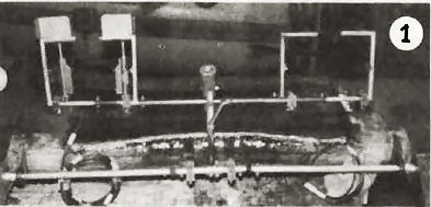
I modified the elevator control system (Photo 1) by first removing the two blades from the two Q2CSA8 torque tube assemblies. I connected the two tubes via a short piece of similar tubing that straddles the C/L of the aircraft. I took one of the aforementioned blades and bent it into a gooseneck and had it welded to the elevator static balance arm Q2CSA11. This assembly was then attached to the center of the short piece of tubing. Several holes were drilled in a vertical line in the gooseneck blade to which the forward of the control stick connecting rod assembly can be attached. The extended end of the gooseneck has a hole spaced approximately 1 1/2 inches off the aircraft C/L. The pitch trim cord, from the control wheel mounted on the forward end of the center console, is attached to the gooseneck at this hole as well is a tension spring running forward to the magneto box. The purpose of the spring is to allow the pilot to override the trim system to make flight corrections without degrading the initial trim setting. A cord from the spring engages a horizontal pulley; mounted on the magneto box, with a 180-degree wrap then returns to the opposite side of the pitch-trim control wheel. I built five spokes into the control wheel, instead of the per plans solid disk. Along side the control wheel I installed a "cabinet-type" sliding latch made of 1/4-inch wood dowel. This system seemed much more positive than the plans type friction device.
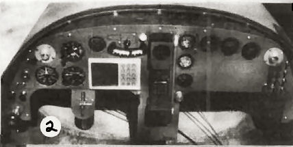
I've also designed and built the detail parts for yaw and roll trim systems that I'll discuss now briefly. The yaw-trim control wheel is mounted on the lower instrument panel between the pilot's knees (Photo 2). There are two pairs of small swivel pulleys mounted on the aft side of the firewall. One pair is mounted about the same level as the bottom of the instrument panel and about 1 1/2 inches on either side of the trim-wheel C/L. The other pair is mounted so as to be aligned with the tabs welded to the outside of the pilot's rudder pedals. Again, tension springs are installed on the forward ends of these tabs with cords attached to their forward ends. These cords extend forward thru the lower pulleys then upward to the upper pulleys then aft to either side of the yaw-trim-wheel.
The roll-trim was a little more complex. The roll-trim-wheel is located at the lower end of the vertical seat back. The wheel is mounted on the aft side and extends thru a slot in the seat back. The aileron torque tube is cut at a point directly below the axis of the roll-trim-wheel. A 5/8 OD tube extends from the tube at this location and engages a phenolic bearing that extends from the aft side of the canted seatback. This horizontal tube is retained by washers and cotter pins on either side of the 5/8 tube. Near the ends of the horizontal tube holes are drilled for tension springs oriented vertically above the tube. Cords extend from these springs upward to the axle of the roll-trim-wheel. On the aft end of the aforementioned 5/8" OD tube extending from the aileron torque tube, I mounted a U-joint which is required to accommodate the vertical movement of the reflexor system.
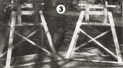
In preparation for mounting the wing and canard to the fuselage, I designed and built a pair of tall sawhorses to which I've added vertical and pitch adjustment capabilities. (Photo 3) The horses in the tall mode will be for supporting the wing after which I'll remove a portion of the legs to lower the horses for mounting the canard. The adjustable portion of the horses have rubber covered pads mounted on wood U-joints that contact and support the weight of the wing or canard.
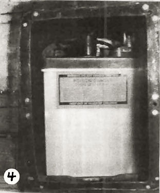
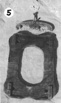
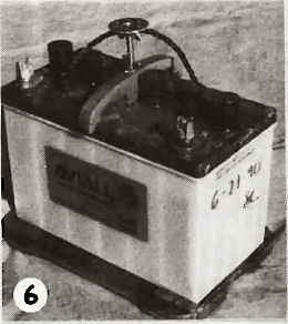
I've located my battery box in the tailcone just aft of FS 120 (Photo 4). Aircraft batteries generally come in two sizes for the 0-200 engines; 25 and 35-amp hour. The only difference between the two is approximately 5 pounds and two inches in length. To retain the batteries I designed and built a wood base plate with a recess on one side to accommodate the 25-amp battery and on opposite side to accommodate the 35-amp battery. The retention device is the same for either battery and is as follows: (Photos 5 & 6) - a 1/2 inch thick piece of wood (narrow enough to fit between the two center filler caps) with an upper surface shape of an oval split along its major axis and lower shape such as to clear the "bumps" on the top of the battery. The extreme ends of the piece extend down to bear on the battery on the outside edge of the battery. At the center of the upper oval surface is installed a "star nut". An oval headed screw with a wing nut shear pinned to it near its head and another locking wing nut is installed into the star nut. On the ceiling of the battery box and in line with this screw is a large washer. With the battery setting in its wood base plate and the semi-oval retaining assembly mounted in the center of the battery the wing nut attached to the screw is turned in such a way as to push down on the battery and up against the washer on the roof of the box. Then the second wing nut is torqued against the star nut to lock the adjustment in this position.
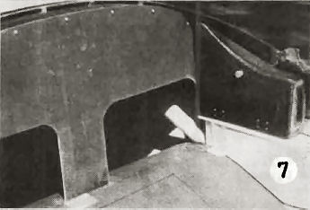
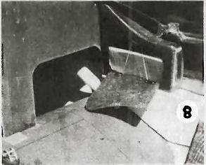
The outside three inches of my instrument panel is useless because just behind it is the wall of the fuel filler pocket. In this area there is just enough room for the instrument panel support bracket bonded to the wall of the fuselage. This bracket contains three nutplates to support the panel. I decided I'd use this area to support a map case I made utilizing the "lost foam" method of fabrication, which is similar to the "lost wax" method of metal casting. (Photos 7 & 8) I carved a shape for the case to conform to the angle of the instrument panel and the IML of the fuselage. The width was equal to that of the right hand console. The fore and aft length was that excess arm rest between my fingers and the instrument panel when my arm was placed on the console with my elbow against the canted seat back, which turned out to be approximately 12 1/2 inches. After the foam carving is completed I covered the foam with Plaster of Paris to fill the pores, ala micro. When the plaster has cured it can be sanded to a smooth surface. Then the entire plastered surface is covered with Vaseline (as a releasing agent) followed by several laminations of BID glass. The BID is easy to "finesse" around compound contours. I choose to use the aft vertical surface as the open end for the glass bag. After the glass cures the "puckered" ends of the glass is cut away. Next, all the foam is removed through the opening. Since the white plaster is a contrasting color of either the blue or orange foam, it's easy to ascertain when you are getting near the inside of the glass because the plaster is exposed on the inside of the glass. This is especially important when digging the foam out of narrow, deep crevices, thus preventing damage to the part. Next a door is cut in the side of the map case. This door also provides access to the inside of the case, which is helpful in plugging the hole in the aft surface where the "pucker" was removed. Now just add hinges to the door that was removed along with a magnetic cabinet latch and you've just made yourself a handy map case. The three screws that hold the instrument panel to the fuselage brackets are now installed thru matching holes in the forward face of the map case to retain it. I strung a rubber band around the hinge rivets to resist anything from falling out of the case when the door is opened.
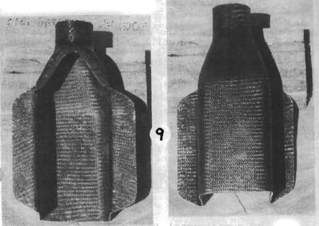
I have used the above described "lost foam" method to fabricate numerous items throughout this project, i.e. an adapter between the carb heat box and the carb inlet duct. (Photo 9) This required a transition from a 2 1/2 ID round to a 1 1/2 x 3 1/2 oval over a distance of 1/2 inch. It worked out real easy. I've also fabricated a gascolator-cooling shroud shaped somewhat like an old glass milk bottle, how many of you remember them? The bottom of the bottle was uncovered and when the glass had reached the "knife trim" stage while curing, I slit one of the large vertical surfaces down the middle horizontally where the bottle starts to neck down. I then turned these two flanges outboard 180 degrees from their original position, thus creating two shroud-mounting flanges. Wherever ducting is going to be clamped later, I'll add several plies of glass to reinforce the clamping area. I could go on and on about this method of fabricating many components, but I think you get the gist of how this process is utilized.
My instrument panel was an interesting project that I'd worried about for quite some time about how I would stiffen that 1/8 inch plywood with a single BID lamination on each side. Although this layup seemed pretty rigid before I started cutting holes in it, it was quite flexible afterwards. I solved this problem by floxing a strip of panel material 1 1/2 inches wide all the way across the panel along the lower edge of the knee cutout. I also ran a vertical stiffener at the center of the panel. These plus the vertical stiffeners to support the Loran-C trunnions and the one I added adjacent to the yaw-trim-wheel was a big help. As a final effort I fabricated a closeout between the top of the panel and the contour at the contour of the forward end of the canopy/fuselage interface by cutting a Masonite pattern of the panel. I then took a six-inch wide piece of aluminum gutter flashing material and formed it to the contour of the panel with gray tape. A heavy layer of Vaseline, four layers of BID and Wallah! a contoured, stiffened closeout panel. On the forward end there is a 3/8 gap between the glass-to-glass closeout of the fuselage. Small spacers attach to the inside of the fuselage/canopy lip at each of the screw attach points provides the necessary rigidity. The wide gaps between the attach screws allows any heat (or cold) that is trapped behind the panel to escape, thereby providing a uniform temperature through the cockpit.
For my initial radio, I'm mounting a handheld with VOR capabilities at the center of my instrument panel. (Photo 2) These two features require two differing antenna requirements for optimum performance. The communication antenna should be mounted vertically while the navigation antenna should be mounted horizontally. I have both antennas installed in their respective optimum orientation beneath the fiberglass lamination, i.e., comm antenna in the vertical fin and the nav antenna in the lower surface of the canard. Behind the panel I mounted a two-antenna input/one antenna output selector switch, with the selector knob on the front of the panel. Since a reach to the radio is required to change from a VOR frequency to a comm frequency (and vice versa), I have imposed an additional requirement of one antenna to the other. The single output antenna is a short pigtail about eight inches long that protrudes thru a hole from the back to the front of the panel then to the top of the transceiver. I installed a three-sided bracket (two sides and a top) over this hole and use it to support my magnetic compass. Since the transceiver is actually operated by a battery, I've inserted the transceiver into the charger and mounted them both on the panel with the charger hooked up to the aircraft's electrical system. I cleared this idea with a technical rep of the transceiver's manufacturer.
I'd appreciate any comments or suggestions from any of the builders.
Dick Barbour, 2405 Sequoyah Dr, Rodgers, AR
(501) 636-8367
Ed. Note: Wheeew! Now THAT'S what I call a progress report. Thank you!
Dear Jim and Tom
Q2 84JS has 380 hours on it. Recently the Revmaster was fitted with new heads because hairline cracks between the spark plug and valve were found. I suspected the push rod tubes were the source of some moderate oil leaks. Replacing them with new tubes and gaskets reduced the engine leaks to almost nothing. Before installation, each tube was elongated to ensure a tight fit.
John Schnackel, Fort Doge, IA
Dear Mr. Masal,
I am a Brit living in Germany and have just completed six and a half years of work on building a Q2. It has only recently been brought to my attention that the QBA existed and I must say I wish I had know sooner as it could have saved me some severe heartache, however, it's never too late and I would therefore like to become a member.
Whilst writing I would be most grateful if you could give me some urgent assistance. After some six hours flight time the aircraft had a slight mishap, the tailspring snapped, and I have so far been unable to locate a replacement. The major problem seems to be that no one knows the specification or source of supply of the spring. What I don't want to do is use something of the wrong type and end up with having to redo this job. So is it possible to help by either:
a) Letting me know where I can get a replacement.
b) Confirming if the G-10 glass epoxy rod offered by Spruce is suitable or not.
c) Placing an advertisement in the newsletter and hope that there is a Q2 owner who can help.
Thank you in advance, and I look forward to receiving my newsletters.
Terry Francis
Ed Note: Long time members know that Aircraft Spruce & Specialty Co. has the replacement tailspring in glass and also the oval type from the Dragonfly, which I have recommended. Many other materials have been used for tailsprings - all apparently equal to or better than the original. 4130 steel tube would be a simple solution.
Dear Jim
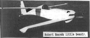
I thought I'd send you a quick note to pass along a couple of tips I've picked up lately that really made a difference in the way my 503 Rotax is running.
First Item: I've been running a high EGT at cruise and no jetting change seemed to help. I called the guy (I forgot his name) at Green Sky to see what he said about it. He nailed it immediately. I had extended my carburetor vent tubes out the bottom of the cowl and this is wrong. If the tubes are in the slipstream it pulls a vacuum on the float bowl and the carbs can't draw fuel. A big THANKS to the guy at Green Sky.
Second Item: A guy from Alabama names Chris Barber wrote to me to share experiences with his 503 Quickie, and he had the same engine bogging problem I'd experienced. I cured mine by putting on a finer pitch prop, but was never happy with the performance. He came up with extending the header pipe two inches just ahead of the muffler, so I tried it. Amazing difference! It lowers the powerband so that I can turn a prop fast enough to take off without the Rotax bogging down. I'm back to my original Prince prop and cruising 130 with normal EGT's. Life is good. Can't wait for the upcoming fly-in season. Hope to see you at Oshkosh this year if everything works out.
Robert Bounds
Ed Note: Now see, this is the kind of nitty-gritty operations details that you other Rotax operators need to be sending in (get that, Hardy?)
Dear Jim
Now guess what? I have just got my C of A No. PF171 for Q1, Rotax engine and all, the first one in the country. On the certificate, the year of manufacture is 1983. The little piece of paper was an anticlimax, you would think something that takes eight years to make would be quite large.
I must admit the Q didn't just stay in the shed. Have flown in some heavy rain, the first few drops give you a fright, but a little bit of backpressure and some throttle, plus the Q will even climb. The official test pilot who flew my Q with a take-off weight of 255 kg said the Q will climb 1100 ft a minute, that OK?
Gordon Laubsch, South Australia
Ed Note: Oh my God, where's my reference book. What the heck is 255 kg?
Dear Quicktalk
Glad to hear from David Fulper that someone managed to drive through the rain in a Quickie without hitting the ground.
I had a forced landing in a Q-1 while over the Flint Hills country in Kansas. During the first 10 to 15 minutes there wasn't much stick force. But ...!!! after 20 to 25 minutes of flying through light showers the Quickie began to pitch nose down. The raindrops would form BB size bumps on the first 50% of the canards airfoil. After the rain drops passed the halfway point they would begin to pool.
The Quickie was by now at full throttle, showed 85 mph on the airspeed indicator and was going down at over a 1,000 feet per minute. The elevator was full down and pools of water 1/2" deep and 4 to 5 inches wide had formed just in front of the hinge-line of the elevators.
Please Jim! Warn those other Quickie pilots that if they still have the old airfoil and are punching through rain, they are playing with FIRE! The vortex generators will correct this major design flaw, which came with the original Quickie. The smart Quickie builders will convert over to the LS-1 airfoil. Terry Crouch has one on the front of his Quickie.
Glad to hear you got a Rotax, Jim, the performance of your bird is going to improve a bunch.
Jim Prell
Let's don't turn on all the sirens at once, Prell. Certainly the LS mod for the Quickie is "nice" but the Q-1's are flying just fine in the rain with the vortex generators. Don't anybody get into a frenzied panic over this, OK?
You can order a PDF or printed copy of Q-talk #33 by using the Q-talk Back Issue Order Page.