Q-talk 64 - QUICKIE (Q-1) REFLEXOR
- Details
- Category: Q-Talk Articles
- Published: Monday, 30 June 1997 07:11
- Written by Terry Sickler
- Hits: 2772
FABRICATION OF DETAILS
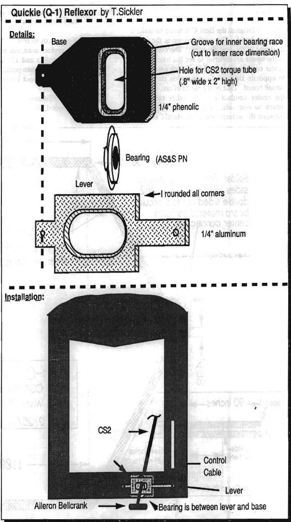
1) Procure a main bearing for an Asuzalite wheel. AS&S has them as does other parts suppliers, I am sure. This bearing has a flanged outer race and the inner race extends beyond the back of the bearing (see drawing).
2) Fabricate the BASE from 1/4" phenolic. Mine is about 4" wide and 3" tall. I rounded the corners so there are no sharp places for things to snag on. Cut the phenolic base similar to the drawing. Locate and drill the pivot hole (I went with a 10-32 bolt). The length of this bolt will be determined at the time of installation. Cut the vertical elongated slot for the CSA3 torque tube. It should be centered and vertical at 2" from the pivot hole. Use a Dremel with a rotary file to cut the groove for the bearing inner race extension. It should be slightly larger and deeper than the race extension. Sand the interfaces until the race extension slides smoothly throughout its range of motion. Do not sand or mar the glossy finish on the frontal face of the phenolic.
3) Fabricate the LEVER from 1/4" aluminum (2024-T3). Mine is about 6.5" long and 2" wide. I rounded the corners so there are no sharp places for things to snag on. Cut the aluminum lever similar to the one drilled into the base. Cut the elongated slot to match the bearing outer race per the drawing. It should be centered and horizontal at 2" to center from the pivot hole. Sand the backside lip of the hole to match the rounded contour of the race. The cut will be sharp and the bearing is slightly rounded so if you do not do this, the lever will score the bearing race. Use a Dremel with a rotary sanding drum to smooth the walls of the hole. The hole should be slightly larger than the outer race dimension. Sand the interfaces until the race extension slides smoothly throughout its range of motion. Do not sand or mar the glossy finish on the frontal face of the phenolic.
INSTALLATION
1) Temporarily attach the BASE and LEVER together with a 10-32 bolt through the pivot holes. Trail fit the BASE and LEVER assembly to bulkhead FS89. Ensure that the lever clears the rudder cable extending back to the tail wheel. Locate the place to drill the pivot hole into FS89. Locate where the aileron torque tube will cross through FS89 and mark. Disassemble the BASE and LVER. Use the base only as a template to locate the vertical slot for the aileron torque tube. Cut the slot in FS89 slightly larger than the slot in the base so FS89 will not interfere with the operation of the reflexor. Bevel the backside of the BASE so that it will be as close to perpendicular to the aileron torque tube (CSA2) as possible once mounted. I used a belt sander to do this very effectively. Determine the proper length for the 10-32 pivot bolt (Allow for three washers.)
2) Index the base to FS89 by placing a 10-32 bolt covered with a mold release agent through the pivot hole. Align the vertical slots and flox the BASE to FS89 and clamp. I also micro'd around the slot in FS89 for durability. Allow epoxy to dry completely.
3) Place the bearing on the base, outer race facing aft, and the LEVER over that. Install the pivot bolt with washers at each interface. Should have three washers: Bolt head-Lever; Lever-Base; FS89-Nut. Route a push-pull cable from the cockpit through FS89, to the LEVER. Attach the cable to the end of the LEVER using the attachment system of your choice. I used a loop on the cable, a bushing and bolt/washers. Make sure you have the capability to move CSA3 up 1/2" and down 1" from a neutral position and a provision to adjust this travel. I used a cable block mounted on FS89 near the end of the reflexor cable shroud.
4) Install CSA3 to CSA2 per the plans, running CSA3 through the bearing as you would have done with the stationary CS4.
5) The reflexor, when properly adjusted, should yield aileron travel of about 1/4" of aileron down and 3/4" of aileron up. Be very careful when testing this control, it is capable of injecting significant control input and also may limit aileron travel if fully deployed. Test it gradually and at a safe recovery altitude.

Terry Sickler, Castle Rock, CO
(303) 688-6099
You can order a PDF or printed copy of Q-talk #64 by using the Q-talk Back Issue Order Page.


