- Posts: 47
- Thank you received: 1
Login Form
Q2 and Q-200 Airfoils
14 years 5 months ago #822
by NateD2
Replied by NateD2 on topic Re:Q2 and Q-200 Airfoils
Dan,
You are right. I originally asked someone to verify the airfoils for me. It appears the LS(1)-0421 mod as listed for the Q1 at the airfoil database isn't the same as the actual LS(1)-0417 airfoil you mentioned.
It appears the Eppler 1212 mod is the correct one (as I listed below). The only question I have is whether it is the Mod or the regular 1212.
Here is a comparison of the LS(1)-0421 Mod and LS(1)- 0417 mod airfoils:
www.worldofkrauss.com/foils/show_compare...%5D=445&id%5B%5D=803
www.worldofkrauss.com/foils/show_compare...B%5D=63&id%5B%5D=796
As you can see from the data the main problem with the 0421 is a 5 degree difference in the stall angle. Additionally the 0421 has a higher peak lift coefficient and more drag.
Compare the 0421 to the 1212 and you see that they have the same basic stall angle. In a canard that isn't what is desirable, which is why the 0417 is a slightly better choice. As the 0421 will reach stall at 10.5 degrees and the main wing will still be producing lift (assuming the angle of incidence to the fuselage is the same).
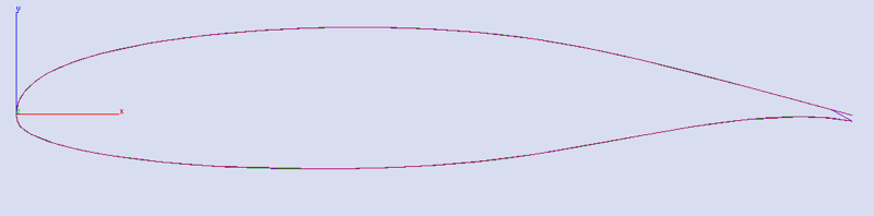
Here is the LS(1)-0417.dat airfoil plotted in my CAD program.
You are right. I originally asked someone to verify the airfoils for me. It appears the LS(1)-0421 mod as listed for the Q1 at the airfoil database isn't the same as the actual LS(1)-0417 airfoil you mentioned.
It appears the Eppler 1212 mod is the correct one (as I listed below). The only question I have is whether it is the Mod or the regular 1212.
Here is a comparison of the LS(1)-0421 Mod and LS(1)- 0417 mod airfoils:
www.worldofkrauss.com/foils/show_compare...%5D=445&id%5B%5D=803
www.worldofkrauss.com/foils/show_compare...B%5D=63&id%5B%5D=796
As you can see from the data the main problem with the 0421 is a 5 degree difference in the stall angle. Additionally the 0421 has a higher peak lift coefficient and more drag.
Compare the 0421 to the 1212 and you see that they have the same basic stall angle. In a canard that isn't what is desirable, which is why the 0417 is a slightly better choice. As the 0421 will reach stall at 10.5 degrees and the main wing will still be producing lift (assuming the angle of incidence to the fuselage is the same).
Here is the LS(1)-0417.dat airfoil plotted in my CAD program.
Please Log in or Create an account to join the conversation.
14 years 4 months ago #842
by flyeravid
Replied by flyeravid on topic Re:Q2 and Q-200 Airfoils
Hi Nate,
I am very interested in your plans and efforts.
You have put several questions; I do not feel informed enough as to give you answers, but I dare to make some suggestions and comments.
But first, let me ask you a candid question: what is the CAD software you are using? I would like to buy a CAD and graphics program and would appreciate your recommendations.
The airfoils being constructed as a foam core to be glassed over later I imagine that the patterns used to hot-wire the foam can not simply be the airfoils coordinates, not even these scaled down by a certain amount but instead the airfoils coordinates corrected by the formula
Y(s) = y(s) ?? thickness / square-root(1 + y?(s)?)
Where Y(s) is the ordinate of the foam core, y(s) the ordinate of the airfoils profile and y?(s) its derivative; and thickness is the thickness of the laminate, considered to be constant along the perimeter of the airfoil. I could imagine that this relationship could explain some differences between ??aeronautical literature?? and do-it materials.
I want to bring to you attention that this small company
www.eurekacnc.com/Home.htm
specializes in CNC-hot-wiring of foam to ??digital templates??. If some control-cuts would validate their claims of being able of doing high precision cuts I could not imagine a reason not to use their services.
To my modest opinion a new construction of a quickie (or for that matter any one of Rutan??s or else??s glass-on-foam designs) should be considered with today??s materials. I mean, epoxy-carbon-fibre-laminates (instead of fibreglass) and the appropriate today??s foams. I would feel free of having to use the original recipes as a number of serious complications have arisen because of petrol leaks destroying foam cores. I would choose foams accordingly.
Regards Juan
Please Log in or Create an account to join the conversation.
14 years 4 months ago #843
by NateD2
Replied by NateD2 on topic Re:Q2 and Q-200 Airfoils
I currently use Cobalt from Ashlar Incorporated (www.ashlar.com). I also use SolidWorks and a few others as needed.
I follow the math you stated, however shouldn't it be a two parameter equation as both X ad Y need to be variables? I suppose I could treat the variable s as a two element vector containing X an Y.
The big question I have is why I need to use your formula?
Also you may want to repost with parenthesis at the proper places to correctly specify order of operation. As the equation reads presently the last term is: -thickness/(1 + y'(s)^2)^(1/2).
Again I'm not quite following where you are going with the formula.
What type of differences between Aeronautical Literature and do-it means are you talking about?
I had been considering the idea of laser cutting the foam rather then hot wire. It is faster and equally as accurate.
I will consider the CNC-hot-wiring....
the real question with the Q series airplanes is what exactly high precision means.
As to today's materials use... it really gets down to cost on that one. From what I have seen of experimental composites there is a good reason glass is used. 1) It is light enough, 2) it is inexpensive to buy and use and 3) it is strong enough when proper structural techniques are used.
I would love to create a carbon fiber Q series aircraft. However I don't think the build would be popular for cost reasons. This will not however preclude me from looking into the structures and materials using carbon fiber.
In reality I think carbon fiber will be nearly be a 1:1 replacement of glass. I'll have to validate the structures that way. Keep in mind my first goal was to completely reproduce a Q-200 electronically. My secondary goal will be to create variants of it.
Foam choice is important. Admittedly I am not at a point where I am ready to worry about which foams are used as I am still modeling the outside of the airframe.
However you make a good point that the resistance of foam to Petro is an issue.
There are two ways to solve this problem from my point of view. 1) Design a structure which doesn't need the foam core to meet its structural requirements and 2) to use foam that is resistant to fuel and solvent leaks)
I probably will go with option 2. However I will do an analysis without the foam to see what the original Q-200 structure does without it. I suspect that if it was designed right the foam's structural contribution to the strength of the the fuselage is minimal... the wings are a different story. One important thing to keep in mind is that a composite structure can be built that needs no foam core. Once the proper thickness of composite is used it SHOULD be able to handle ALL the flight loads with minimal need to transmit them via the foam. I will have to determine if this is the case or not.
As to the airfoils... the main problem I ran into is the deviation from the published airfoil data while tracing the patterns. There are some mathematical differences in how the data is represented between the two versions of the airfoils in the airfoil data base.
The secondary problem has been in correctly splitting the airfoil at the control area and attaching the proper control geometry mount points to the airfoil segment. I am still in the process of looking over this... so the exterior model of my CAD file is not complete at this point. However soon will be.
Do you have any recommendations for foam? I know there are fuel resistant foams out there. Unfortunately whatever foam I will use I will have to do quite a few structural failure tests on to find out what the transmitted loads will be.
As of now I have not found any database that categorizes foam core composites with glass in compression, shear and tension. Of course this is data I will have to collect and use for the model I am working on in order to being the process of verifying the structures.
Nate
Please Log in or Create an account to join the conversation.
14 years 4 months ago #844
by flyeravid
Replied by flyeravid on topic Re:Q2 and Q-200 Airfoils
Hi Nate, sorry I try to send you a detailed explanation but I do not know why the system does not accept my text. I guess it has to do that there are mathematical simbols, etc.
But a point adress is that in my formula is should NOT be "thickness devided by something" BUT "thickness multiplied by this something".
The argument of the square root is (1+y?(s)?).
And, last not least, I assume that you get the airfoils shape form an aeronautical data base as a function y(s) where s is the position along the chords length.
s has values between 0 and 1.
What I wanted to stress is that if you find a template to hot-wire a quickie airfoil, say the canard, say to a GU25 shape, AND you compare it to an aeronautical data-base AND you find discrepancies between the two, THESE very could be because of the necessary corrections to the foam core shape as pointed out with my formula.
Regards Juan
Please Log in or Create an account to join the conversation.
14 years 4 months ago #845
by NateD2
Replied by NateD2 on topic Re:Q2 and Q-200 Airfoils
I'm still not quite sure I follow you. I know that NACA airfoils have a special equation that relates the y coordinates of the airfoil to the chord position. However this is not true for other airfoils which are experimentally derived not mathematically derived.
In such a case I can obtain the X and Y coordinates that make up the airfoil. These data files express two curves as a series of X,Y points. There is an upper curve and a lower curve both of which have their own coordinate sets where each set could be represented as a vector data type (a matrix of 2 X N dimension) of X,Y points.
Typically there are AutoCAD files for these data types. My CAD program sees the AutoCAD data as a series of segmented lines. So what I do is trace a B-Spline or NURBS Spline over the endpoints of these lines. At present I am evaluating the errors in different ways CAD software can trace these date points into splines. So far it appears the error is less then 1%.
I am hoping to soon double check this error with CFD modeling. However in all reality based on the way real airfoils work I doubt even a 2% change in XY position of any of the data points will adversely effect the flying characteristics of the airfoil.
With that said it is important to note that XFoil and other airfoil software typically use an abbreviated number of data points to perform their math. In this case a comparison of the accepted data base values for a given airfoil and the CAD files generated by these programs that should be done. As you can imagine resampling the data points with various equations is important.
Here is the link for the airfoil database. Note they include a library file of DWG format airfoils in a .zip file near the top of the archive.
www.ae.illinois.edu/m-selig/ads/coord_database.html
At present I directly import the data from the .dat file to generate the spline curve for the airfoils.
My main concern is verifying the airfoils used and then using those numbers in my Stability and control analysis using the DATCOM methods. For this case the numbers for the 3 stability derivatives obtained will be dependent on getting every parameter of the CAD model (and its accompanying geometry) correct.
The reason I don' use the tracing supplied by the plans is because I feel it would be a step backward. Why use a second or third generation copy when you can implement the original airfoil?
My goal is to make the highest quality set of plans available so that any builder can end up with the best quality results. I should make note that tracing the original plans supplied on the web site gives me an airfoil data point accuracy of about 0.020" perhaps a bit less. Using the airfoil data files ensures that the limitation to the shape of the airfoil is strictly a function of the math modeling used by the computer to generate the shape. So when parts are made they should be as perfect as is practicable.
In the attached file (drawn with a chord length unit of 1) if you look at the outline of the various data representations you can see some inconsistencies.
This is the difference between the Airfoil Database AutoCAD file and the raw spline data line created using a B-Spline.
Please Log in or Create an account to join the conversation.
14 years 4 months ago #846
by NateD2
Replied by NateD2 on topic Re:Q2 and Q-200 Airfoils
For some reason the picture would not post so here it is again.
Please Log in or Create an account to join the conversation.
Moderators: JonMatcho
Time to create page: 0.176 seconds
©2024 www.quickheads.com