- Posts: 47
- Thank you received: 1
Login Form
Q2 and Q-200 Airfoils
14 years 4 months ago #847
by NateD2
Replied by NateD2 on topic Re:Q2 and Q-200 Airfoils
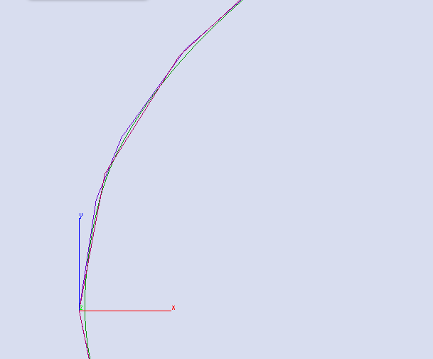
Here is a close up of the leading edge to further show the difference in ways of representing the data.
Please Log in or Create an account to join the conversation.
14 years 4 months ago #848
by NateD2
Replied by NateD2 on topic Re:Q2 and Q-200 Airfoils
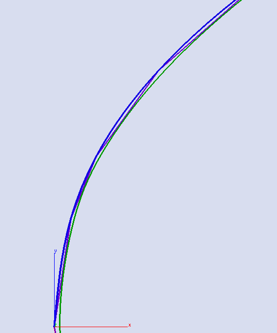
I should note that at a close up scale my CAD program will not draw nice Spline curves to screen (a limitation on the software). However if I scale the airfoil up by a factor of 50 (making it 50 inches long) here is what the exact same thing looks like. Here I have drawn the smoothed splines in Blue. The original data points connected by line segments (coarse) in purple and the "corrected" curves output by the algorithm used by the Airfoil data base in Green. Note the green curves are the nicest however they don't start at the origin. The spline curves on the other hand do, however their tangency at the origin isn't perfect (yet).
Please Log in or Create an account to join the conversation.
14 years 4 months ago #849
by Leon
Replied by Leon on topic Re:Q2 and Q-200 Airfoils
NateD2 wrote:
>>The reason I don' use the tracing supplied by the plans is because I feel it would be a step backward. Why use a second or third generation copy when you can implement the original airfoil? <<
I agree completely and that is how I generated my CAD files for the Quickie's airfoils. I then offset the curves to allow for the thickness of the skins as needed.
Also keep in mind that if you closely examine an original set of plans you can see the remnants of the grids to HAND loft the templates from the ordinates. Considering the tools of the day QAC did a pretty good job.
======================
Leon McAtee
Please Log in or Create an account to join the conversation.
14 years 4 months ago #850
by flyeravid
Replied by flyeravid on topic Re:Q2 and Q-200 Airfoils
Hi Nate,
I took a look at the airfoils profile data of the NASA/LANGLEY LS(1)-0421 AIRFOIL
To be found in www.ae.uiuc.edu/m-selig/ads/coord_database.html#L.
as an example to test, and, yes, although the data are given to 10 high minus 5 of the chords length there are bumps in the airfoils profile suggesting that the data my have errors.
A laminar airfoil of a typical chord of 1 meter should be constructed with a maximal waviness under 0,1mm and the profile resulting using these data I refer to has waviness above this limit.
I tried smoothing it and found best results when approximating using AKIMA??s cubic splines. When using my approx-interpolations program I can also additionally visually change interpolation points and using this feature I was able to smooth the curve ??satisfactorily??. I am not that firm in aerodynamics as to dare to affirm that these changes I did would not have an effect of the gross aerodynamic properties of the airfoil. But I believe, that they are unimportant. And I believe that smoothing out the waviness is definitely necessary.
As concerns my ??formula?? I see I have not succeed in making my point clear to you.
I try again:
If we have a look at the set of data points for an airfoil
/LANGLEY LS(1)-0421 AIRFOIL
38. 38.
0.00000 0.00000
.00200 .01560
.00500 .02377
.01250 .03599
.02500 .04912
.03750 .05853
.05000 .06606
.07500 .07771
then the entries of the left column are my ??s?? (you call them ??x?? ) and the entries in the right column are our ??y?? and also my ??y?? but I write them y(s) as their value is given by ??s??. ??s?? attains values between 0 and 1.
If you wish to fabricate an airfoil with a profile matching those ??s?? and ??y(s)?? as above AND if you will construct that airfoil as a laminate OVER a foam core, then you should not hot-wire the foam to this same profile, because applying the laminate on top of the foam will change the dimensions. What you have to do is to reduce the dimensions of the foam core by an amount given by the thickness of the material you will apply. So the shape of the ??reduced?? core is not given by the above set of data points s, y(s) but by a different one s, Y(s) and I gave you the formula
Y(s) = y(s) ?? thickness x square root of(1+ y?(s)?)
relating both sets.
As above, s is between 0 and 1
(This formula has to be appropriately understood for s < thickness and for s > 1-thickness, there the ??reduced?? foam core has disappeared).
Inversely if we find an original pattern for hot-wiring a foam core to, say, a GU 25 profile, do not expect it to match exactly to the GU25 data set in aeronautical data bases; they must differ for the reasons I am explaining.
Of course we should pose us the question: And if we do not correct the shape of the foam core as described, does the resulting deviation of the shape of the airfoil from the desired GU 25 shape have any importance? Well, a back of the envelope calculation tells you that we then increase the wing surface by 1,8%, we change maximal thickness from typically 17% to 16,5% this having some consequences on maximal lift coefficient and stall angle and we make a definitely blunter airfoil nose. But again I do not feel aerodynamicist enough to judge.
This and only this I wanted to suggest. I now hope that I succeeded clearly expressing what I wanted to say.
As concerns your comment on not using sandwich composites but a single layer of laminates instead, of course, you easily get strong enough structures with them. Here in Europe we have different AC using this single laminate techniques, Pipistrel??s Sinus and Virus, Remos, CG??s, and many other . You get fuselages for LSA??s with typical weights in the range of 35 kg. BUT forget using the technique of ??moldless composites?? with them, you have to construct a negative mold that is very expensive and makes sense only if you think of laying up a series. Besides this, although you finally get heavier structures with sandwiches, you get a number of advantages also. Impact resistance of a sandwich laminate is orders of magnitude above that of a single laminate and so passenger protection. Thermal protection also. Imperviousness to resonance effects, jerry-canning for example, resistance to twisting and bending forces are orders of magnitude higher with sandwiches and this dispenses of having to go through difficult calculations on oscillation frequencies and damping.
Regards Juan
Please Log in or Create an account to join the conversation.
14 years 4 months ago #851
by NateD2
Replied by NateD2 on topic Re:Q2 and Q-200 Airfoils
I think I follow your thinking with the airfoils.. however I think there is a simpler solution. In my CAD software I have a tool that offsetsthe curve by some user defined value. In the case of the airfoil it allows me to create a perfectly parallel curve. The secondary option of course is to just scale the chord length in X and Y by some value equal to:
If I need a larger core:
(Desired Size/current size) = a value greater then 1.
If I need a smaller core:
(Desired Size/current size) = a value less then 1.
Of course desired size exists as a function of ANY geometric reference chosen on the airfoil. I usually use a chord line or a thickness line. In this case you simply add/subtract 2* thickness of the laminate to the current size of the part.
In this way the whole airfoils scales and allows a uniform composite to be added to it and retains its original shape.
This in my opinion is the simplest way to solve the problem as all airfoils generated are geometrically similar to the original.
Beyond the differences in how the CAD software connects the lines I really don't see any deviation of shape of the airfoil. If I pick the right airfoil and it matches the patterns supplied I can scale it to any size and its performance will be a function of a few parameters (mainly reynolds number) which I can verify with various algorithms out there. This said I full well expect the airfoil characteristics for a unit chord length airfoil and one 10 feet long to be nearly the same with using proper simility technique (buckingham pie theory comes to mind).
In either case I don't think a change in chord and thickness of the airfoil by 1/4 or 1/2 an inch is going to effect the airfoil qualities that much. However... once I get my model established I will verify this with proper math for lift and drag and stability. i will adjust things as needed if they appear unsafe.
You are right in the concept of your assessment of the the 1.8% area change and the 0.5% change in thickness. Since I have not run the numbers at present I can tell you that the lift coefficient should not change much. This is because the definition of lift coefficient is almost always constant for similar airfoils in subsonic cases. However when you use the lift coefficient to calculate the lifting force created by the wing it is a function of Reynolds number. One of the inputs for the Reynold's number is the reference length of the object in this case the chord length. So with that said the equations take care of these changes. The result is that the Cl vs Alpha curve will remain nearly the same with small if any changes. The Cd vs Alpha curve will also remain nearly the same.
In fact there is a reason that almost all airfoils in the database are drawn with a chord length of 1. 1 is the accepted unit length of the chords for airfoils. There are equations that allow designers to get a good feel for the properties of both wings and airplanes based on these the data for each airfoil. In the case of wings the lift of a wing is really a function of several things: chord, span, aspect ratio, twist sweep, dihedral/anhedral and alpha.
In the example you provided of a 1.8% area increase and a .5% thickness increase as the designer I can fix the problem in several ways. The easiest it is to explain my CAD methods so that you realize the issue isn't a problem. But another way is to alter the span of the wing to correct the effective area or vary any linear combination of the parameters I listed above. These would ALL allow for a change in lift. This is of course why many aircraft can exist with such different and varied wing designs. It is in the designer's hands to make the needed lift and figure out HOW to do so based on what they feel the flight characteristics of the airplane should be.
In my case I am simply figuring out where the Q series airplanes are and allowing for sub-revisions to be improved to where they should be (if any changes are required).
With that said the blunter airfoil nose isn't an issue because airfoils are scalable even with a blunter nose the rest of the airfoils has grown to match the change in the nose and the flow around the wing remains largely unchanged.
Sandwich composites are an interesting topic. They provide a lot of benefits structurally. However my response was in reference to your concern about the foam melting with gasoline or petro contact (or any solvent for that matter). In that regard one needs to either design the wings to not rely on the foam OR use a fuel resistant foam.
Personally I would almost prefer not relying on the foam. However to accomplish this there are a number of trade offs to be made. Weight is the biggest of them.
I am pretty sure Lancair uses minimal core composite on their wing structures (not sure about their fuselage).
I can't comment on resonance effects without mentioning that the stiffness change with core composites and core-less composites is much different for the same weight.
I personally would perform oscillation frequencies even on core composites.
Please Log in or Create an account to join the conversation.
Moderators: JonMatcho
Time to create page: 0.268 seconds
©2024 www.quickheads.com