- Details
-
Category: TriQ Plans
-
Published: Wednesday, 29 December 2010 00:00
-
Written by Scott Swing
-
Hits: 11902
The belly board was developed to provide an effective means of increasing the rate of descent and preventing excessive float on landing.
It is designed to operate in the speed range of 120 MPH down to minimum pitch buck speed. In the prototype, no adverse conditions existed that prevented use through this speed range. Take-off and climb to 4500 ft. at 1000 Ibs. gross was accomplished with full deployment. Rate of climb suffers/as you might know but it can be done safely.
CONSTRUCTION
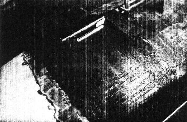
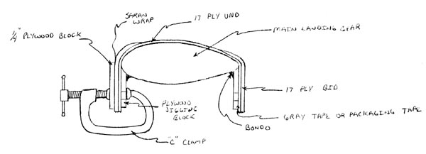
The board is made trom the piece removed for main gear installation and cannot be fitted until the glassing is complete for the main gear. The board is hinged from the rear and cable retracted.
STEP #1. Trim board until it fits within the space provided. This should be done with the main gear installed and the gear to fuselage fairings installed.
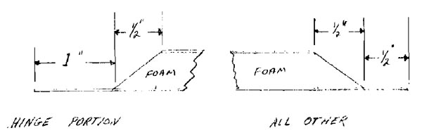
STEP #2. Trim inside foam as illustrated:
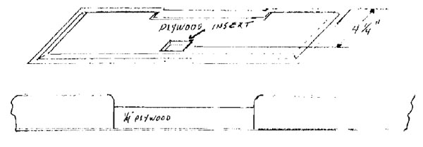
STEP #3. Cut a piece of 1/4" plywood 1-3/4" x 1-3/4" and micro into foam cut out as illustrated:
STEP #4. Glass over entire inside surface with one layer of bid cloth. Add one extra layer of bid at the hinge attach area. This will be a 2" x 12" piece of cloth.
STEP #5. Trial fit board into position and trim to approximately 1/16" gap all around. Main gear can now be removed.
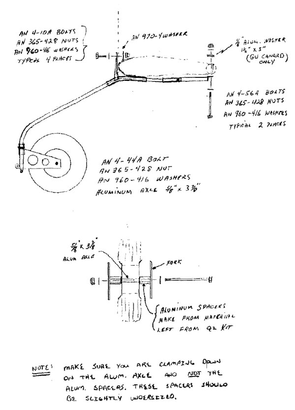
STEP #6. Trim MS 20257 P4 aluminum hinge to approx. 11-1/2" Drill 12 - 1/8" holes equally spaced on both sides of hinge.
Cut hinge pin to 11-1/4" and install in hinge. Crimp both ends of hinge to hold pin in position. This can be done with a flat punch and hammer. (Some hinges may already have hinge pin installed)
STEP #7. Hinge can now be installed onto speed brake by clamping to the aft side of board, centered, with approx. 1/16" of the hinge extending beyond the aft edge of board.
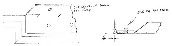
Drill the 12 - 1/8" holes from the hinge side. If Clecos are available, use on every other hole to ensure alignment. Countersink holes and attach using the BSC 44 flush pop rivets.
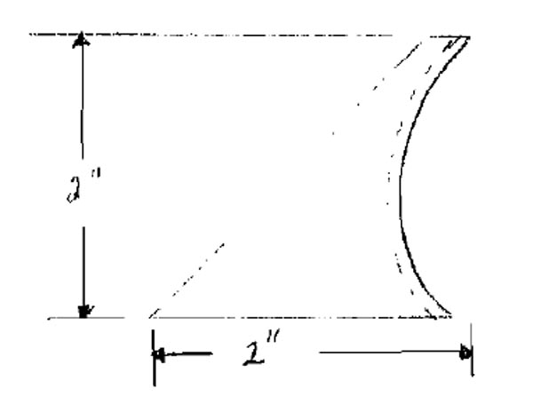
STEP #8. Drill the 1" x 1" x 1" aluminum angle with two 5/32" holes and one 1/4" hole as shown:
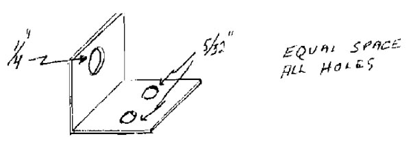
STEP #9. Attach the 1" x 1" x 1" aluminum angle over the previously installed 1/4" plywood plug, using the MS 24694-S9 FH machine screws and AN 364-B32A nuts.
STEP #10. Using C clamps, install board into position clamping hinge to the previously installed bulkhead. Adjust so board is flush with bottom surface of aircraft.
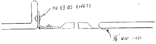
Drill and install AD 43 BS pop rivets.
STEP #11. Apply bondo to both front corners of board and close to align leading edge with fuselage. Hold until bon do sets.
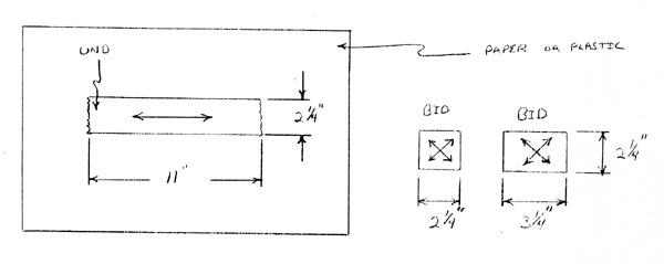
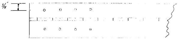
STEP #12. Apply a 3/8" piece of thin tape (plastic packaging tape works well) along the fuselage just ahead of speed brake. Sand 2" back of front edge of board and 2" in front of board on fuselage to prepare for glassing.
STEP #13. Cut two pieces of bid cloth; one 4" x 24" and one 3" x 24" and apply equally spaced over previously prepared surfaces.
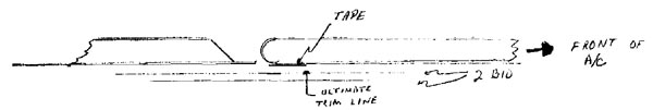
When in the green stage, knife trim just ahead of tape and let cure overnight.
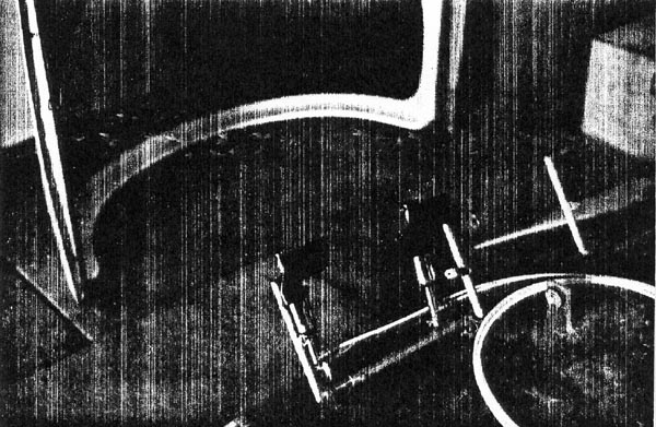
STEP #14. After cured, knock hinged board loose from front edge, remove tape, and sand to a clean fit. With the exception of finish and painting, board is now ready for cable actuator.
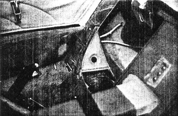
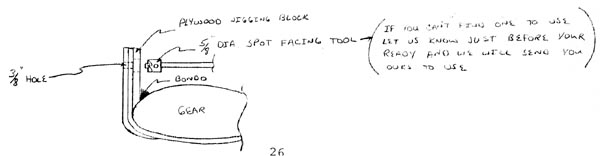
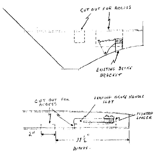
STEP #15. Using the paper, full sized template, cut the 1/8" aluminum actuator bracket and file smooth. Actuator is installed using the hand brake mounting pad and bolts. You will need to make plywood spacers to position bracket for alignment with existing arm rest brake handle cut out. Trial fit and then remove.
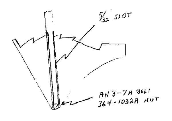
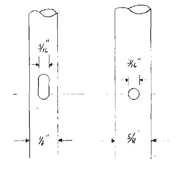
STEP #16. Using the provided 1/2" OD .065 wall aluminum tubing, cut a slot 5/32" wide and long enough to clear ratchet cuts when bolted to the lower attach hole. Slot should not be so long as to allow arm to exte~past rear stop. Temporarily attach with the AN 3-7A bolt and 364-1032A nut.
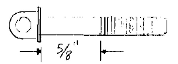
STEP #17. Using the provided 5/8" OD x .049 wall aluminum tubing, cut a 5/32" slot in one end 7/8" up from the end .
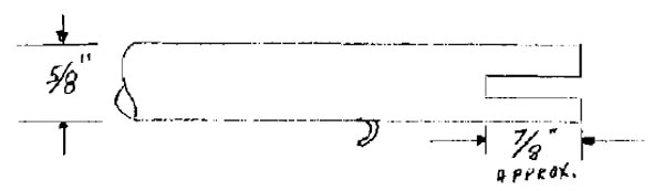
Cut and roll as illustrated for the spring attach. See full sized drawings for instructions. Spring attach tab is cut with a pointed hacksaw blade or numerous small drilled holes connected by hacksaw blade cut.
STEP #18. Slide the 5/8" tubing over 1/2" tubing and align slot over 1/8" aluminum attach bracket with spring tab to the inside (cockpit side).
It will probably be necessary to increase slot depth on the forward side to the 5/8" tubing to provide a solid down seat on the rear slot. Cut the other end of the 5/8" tubing so that at least 3/4" of the 1/2" tubing extends past the end.
STEP #19. Temporarily re-install the bracket into the aircraft and check for fit. Now draw a straight line from the arm rest forward to the aluminum tubing with the tubing in the full aft position (the original slot might need enlarging to achieve full travel).
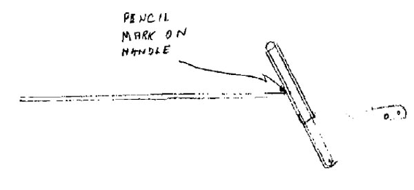
Now remove the assembly from the aircraft, measure down 3/8" and drill a 3/16" hole through both tubings.
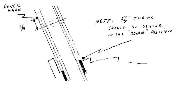
Remove 5/8" tubing from 1/2" tubing and proceed to elongate the 3/16" hole to make a 3/16" slot. This is done on the 1/2" tubing only. This slot will extend up from the original hole long enough to allow the outer tubing to slide up over the inner tubing (with a 3/16" eye bolt in the hole) so that the two can move through their entire travel. Remember -- the 5/8" tubing will have a 3/16" hole, the 1/2" tubing will have a 3/16" slot.
STEP #20. Re-thread the 3/16" eye bolt (10-32) (AN 42-14) back to within 5/8" of the base.
Install into hole and run the AN 364-1032A nut to where two threads extend through. Install spring and test for full travel.
Re-install assembly to airplane.
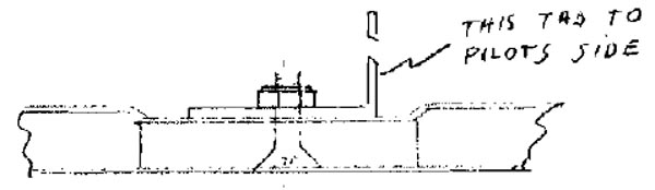
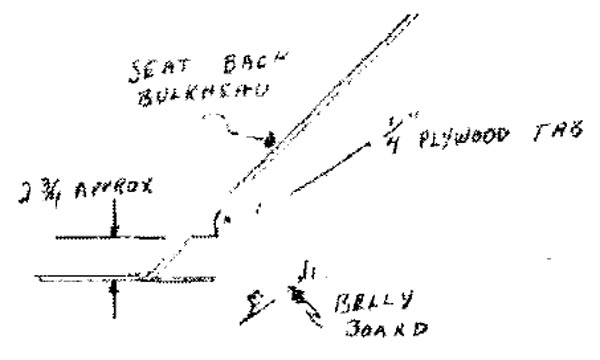
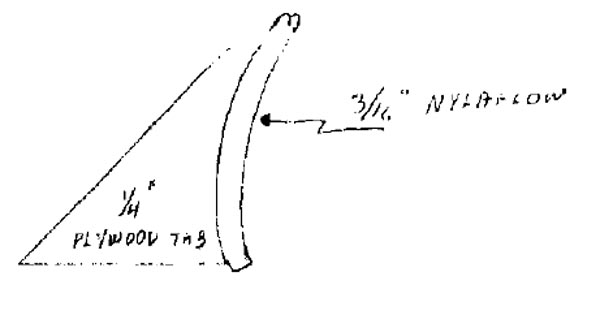
STEP #21. Fabricate a 1/4" plywood plate per picture:
Groove curved section to fit the 3/16" nylaflow tubing. Five-minute epoxy this bracket to the center of the seat back bulkhead in line with the aluminum 1" x 1" angle previously attached to the belly board
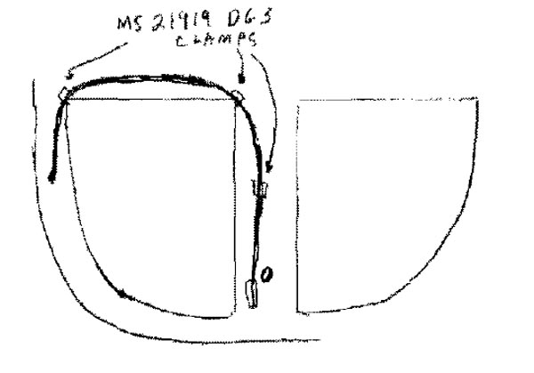
STEP #22. Drill 3/16" hole in seat back bulkhead just aft of pilot armrest and run 3/16" nylaflow through and within 2" Of actuator. Lock in place using one MS 21919 DG3 clamp and surplus 6-32 or 8-32 machine screw and nut.
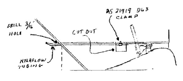
Route the nylaflow up and over pilot baggage opening cut out in bulkhead and fasten in both corners with MS 21919 clamps.
Extend down to plywood tab and five-minute to tab contour.
After five-minute has cured, sand area around tab and secure the tubing to the seat back bulkhead using two layers of bid cloth. Secure tubing every 4" using two layers of bid cloth.
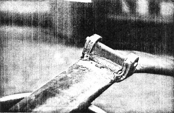
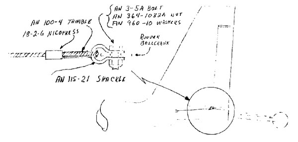
STEP #23. Run 3/32" cable through nylaflow and attach at belly board as illustrated.
Tighten bolt only enough to allow free movement.
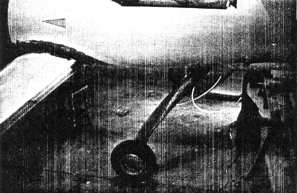
STEP #24. Attach to actuator as illustrated:
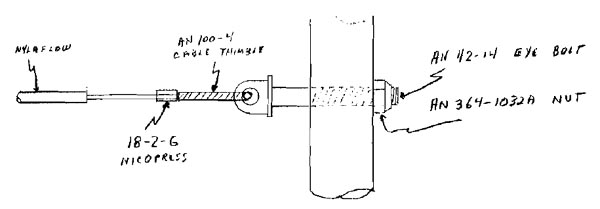
Pull tight before crimping nicropress with actuator arm in the closed position.
Extra threaded portion of eye bolt is for fine adjustment.
STEP #25. Fabricate a wooden plug for the top end of the 1/2" aluminum actuator arm and press fit. (NOTE: Ski pole handgrips work fine for a finished look. 3/4" aluminum thumb portion extends out through the top of hand grip·)
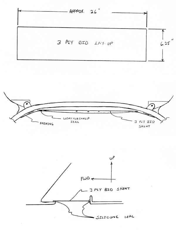
BELLY BOARD HOLE COVER
THE END