Q-Talk 162 - Better LS1 Instructions?


- Details
- Category: Q-Talk Articles
- Published: Tuesday, 31 December 2013 10:35
- Written by Dan Yager
- Hits: 9959
CONSTRUCTION OF LS(1) 0417 MOD CANARD
JIGGING THE CANARD:
Establish a BL15 reference line on the topside of your canard jigging table. This can be done with a long straight edge or chalk line. Locate and mark on your table BL0-0, 15, 48.8, and 100, both sides. Place jig blocks BL15, 48.8, and 100 in their respective places (they are glued to 1/4" or thinner plywood, fiberboard, etc. .). 5 minute or bondo to table shimming for level, proper anhedral, and sweep (see addendum to appendix sheet W-4 8/26/83). (*Also, disregard string hole alignment methods aft end of jig blocks).

Addendum to Appendix Sheet W-4 8/26/83
Note: BL100 blocks will extend slightly outboard of BL100 foam cores since foam core measurement was flat, not at anhedral angle. You can move the BL100 jig blocks inboard to match the cores when trial fitting to spars.
Trial fit both spars at trailing edges (we held ours in place with large rubber bands). Some custom fitting will likely be needed @ BL0-0. Note: 3.5°+ sweep aft of spars at outboard tips.
Sand spars completely for bonding. There is an extra ply of fiberglass on the surface for this purpose. Grind center portion of spars (BL 0-0) at apex to minimize bump. Wear a dust mask when sanding the black carbon fiber. *See 1st sketch page 2.
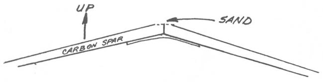
1st Sketch From Page 2
From BL15 to BL100, the hotwire block sizes are exactly the same as called out in the Q2 Construction Plans. . .
Q-2 Plans: Page 5-2
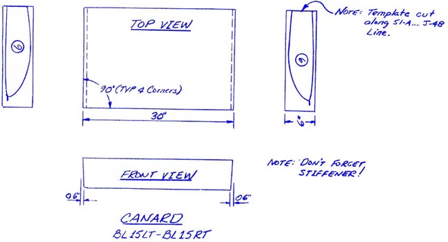
CANARD CORES
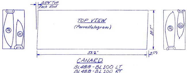
The outboard and inboard canard cores are cut from skewed, parallelogram style blocks, with the exception of the canard center section. The reason for this is to obtain the proper sweep of the canard when the cores are jigged together later.
Begin by squaring up the 10" x 20" X 96" nominal dimension block of polystyrene foam to obtain a length of 51.2", with the skew as indicated. Next, using the sketch provided, hot-wire the outboard canard foam cores. Note that the bottom set of templates are upside down, so as to obtain the proper geometry upon jigging.
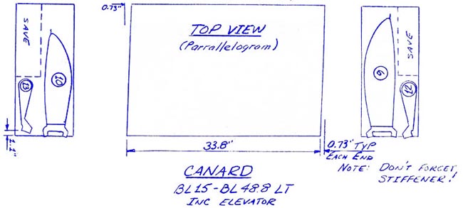
Next, find the extra pieces from the 10" x 24" blocks (2) and face them up to the dimensions shown. These two blocks are used for the inboard elevator cores and inboard canard cores. The portions not used will be used later for the outboard elevator cores.
Don't forget the cutouts for the elevato0 torque tubes. After the elevator cores have been hot-wired, cut along one of the lines (e.g.4-A-B) and hot wire down that slot and around the inside (e.g. 4-A-B-C-D-E-F-G-H-I-B-A-4) and out again. Then cut along the other line (e.g. 4-F) and hot-wire along that slot to complete the cut.
Q-2 Plans: Page 5-3
Finally, locate the remaining part of the 10" x 20" block and size it as shown, in order to make the canard center section. Keep the unused portion for cutting the vertical fin, so don1t make the height over 6.0". Note the the 0.6" taper dimension is to allow for the proper anhedral angle upon assembly in the canard female jigging templates.
Take the two canard template BL48.8 and BL15 and remove the 33-A-B-C-D-E-F-38 notch in each template. Then, hot-wire the canard stiffener out of each inboard canard and canard center section foam core, being care ful to line the templates up properly. Store the stiff eners carefully to avoid damage.
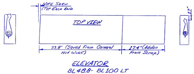
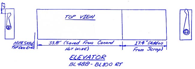
OUTBOARD ELEVATOR CORES
Find the two pieces of foam that you saved after hot-wiring the inboard canard cores. (The areas are marked 'save' on the sketches). Add some additional scrap pieces, being careful to obtain proper skew throughout the setup, and make the inboard elevator cores. The template offsets are necessary to obtain the proper geometry.
Hot wire for the elevator torque tubes like you did on the inboard elevator cores.
. . . From BL0 to BL15, we use 2 pieces instead of 1. The blocks for these should be sized to 15.70" long. These sections are jigged after the spars and other hotwired sections have been located. A bevel will need to be sanded to allow for the canard's anhedral. Trial fit cores in place, check transition alignment, and sweep aft. From BL15 to BL100, you should measure about 10.5" at L.E. foam cores.
Coat the ends of the spars with flox, then bond to the jigs with 5-min micro dabs. Remember the spars must join together perfectly with no joggles. Wipe the excess flox off and if there are no gaps, you may proceed with glassing the spars together. Otherwise, wait until the flox has cured and sand.
Laminate the spars together first with 3 ply BID at 45° extending about 6" either side of the joint. Stagger the plies about 1/2" to 1". Next, the caps are laminated using UNI. These caps are a minimum of 3 1/2" wide and may be laminated on a clean plastic surface prior to transferring to the spars. Since these tapes are narrow and short, you may find it easier to use the selvage edge for one side of each ply. This will reduce the fraying.
We suggest that the bottom cap be laminated at this time and that you wait until the bottom surface of the canard has been covered to do the top.
The lamination schedule for the caps is:
Bottom:
- 5 ply - 18" x 3.5"
- 5 ply - 16" x 3.5"
- 5 ply - 14" x 3.5"
- 5 ply - 12" x 3.5"
- 5 ply - 10" x 3.5"
Top:
- 5 ply - 20" x 3.5"
- 5 ply - 18" x 3.5"
- 5 ply - 16" x 3.5"
- 5 ply - 14" x 3.5"
- 5 ply - 12" x 3.5"
- 5 ply - 10" x 3.5"
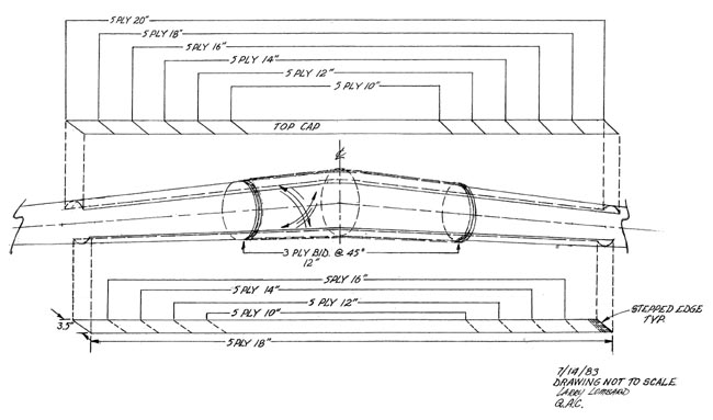
LS1 Spar Cap Lamination Schedule
After the caps are cured, sand for bonding the skins.
The center section cores will need to be modified to allow for these caps.
The canard cores may now be jigged and bonded together. Refer to the Q2 Plans. . .
Q-2 Plans: Page 10-2
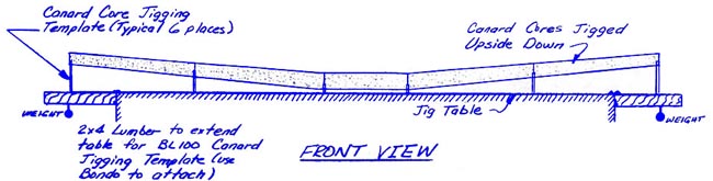
JIGGING THE CANARD
Next, you will need to jig the canard cores on the jig table. It would probably be a good idea to clean off the jig table of any bondo chips, wood, epoxy, etc., so that you start with a clean surface.
Find the canard core female jigging templates (6)
Now study the sketches. The canard cores are jigged upside down on the jigging table using the canard core female jigging templates. If your table is not at least 200 inches long, you will have to extend it like you did on jigging the main wing. As on the main wing, the shear web is perpendicular to WL00, and the canard core female jigging templates have leading and trailing edges that are tangent, respectively, with the leading edges of the canard, and the canard shear web.
Begin by drawing a straight line along your jigging table and marking the locations (BL's) of the canard core female jigging templates. Next, temporarily set the cahard core female jigging templates on the jigging table so that their trailing edges are the distances from the straight line, called out in the accompanying illustrations. Note that the outboard canard core female jigging templates (the ones at BL100 right and BL100 left) are right on the straight line. A string stretched spanwise with a weight attached at either end may be helpful in establishing and keeping the straight line.
Now begin to trial fit the five canard cores into position. Be careful in handling the foam cores to prevent damage to the foam. All cores may have to be sanded in order to make them fit together within the maximum tolerance of 1/16". The canard center section core is already beveled to compensate for the anhedral angle, but it may still have to be trimmed and sanded to obtain the fit on the joint within 1/16". The level lines on all cores must remain level at all times. This is important, so take your time.
Stand back and sight spanwise along the canard to verify that the canard is straight, and is not bowed or kinked. Verify that the leading edges are straight, and that the trailing edges are straight also.
Don't be concerned if the canard core female jigging templates need to be moved inboard or outboard to remove any bows or kinks. Also, a long straight edge will help you looking for kinks and joggles, or dips.
When everything is perfect, mix up some bondo and carefully bondo the canard core female jigging templates to the table top in the necessary location. Next, rest the canard cores on the canard core female jigging templates. Check the alignment and individual level lines again; then again and again until every thing is Perfect, with a capital P. The next step is to join the foam cores together with micro slurry after verifying that the core fit is within 1/16". Check, recheck, and re-recheck each core level line and alignment as the cores are joined.
Note that the canard center section foam core gets a glass rib of 2 BID and flox corners at each end of the canard center section foam core. The flox corner should be added after the entire series of canard cores have been joined and cured.
. . . Laminate ribs of 2 BID at 45° at the BL15 joints. Jig the BL15 to BL00 cores after the ribs are semi-cured (still tacky). . .
EDITOR'S NOTE:
These 2 BID at 45° at the BL15 joint "Glass Ribs" (highlighted in RED above) seem important - Yet there is really no discussion in the Q2 plans about how to create them. In the Q2 Plans the "Glass Ribs" are only hinted at twice in the Materials Education Chapter 3 . . . The first time is the discussion of how to create a flox corner on Page 3-13 . . . and the second is in the filling and inspection requirements on Page 3-16 (Drawing of Section C-C).
Apparently, you were expected to also have a copy of the Q1 plans laying around your shop. There is a slightly better description and drawing of the glass ribs on Page 10-10 of the Single Seat Quickie Plans as shown below.
ADDITIONAL NOTE: The top drawing below refers to the LEFT WING and the RIGHT WING, but shows the canard. Try not to be confused by this.
Single Seat Quickie Plans: Page 10-10

. . . The next step is to join the foam cores together. Glass ribs are layed up at the BL10 joint on each side. The BL49 joint is accomplished with micro slurry. Be sure to use slow epoxy. Refer to the education section for core joining information.
After the combination has cured, cut in the Flox Corners at the BL10 joints. Before doing the Flox corners, however, recheck the level lines at the tips and 5 minute the cores to the templates.

Q-2 Plans: Page 10-2
|
CAUTION |
|
The canard foam cores must fit within 1/16" or exotherm damage may result. Core preparation is the single most important factor in obtaining an accurate, strong, and lightweight canard, so don't hurry through this section unless you don't mind regretting it for years to come. |
PREPARING THE CANARD CORES FOR GLASSING
At this point, the canard cores should be jigged on your jigging table upside down, 5-minuted and bondoed in place, and able to take a direct hit from a 88 mm howitzer without budging from its location.
Use a hard block to clean up all joggles, excess micro, and any bumps on the canard cores. At either end of the canard center section core, round the joint so that the glass will flow smoothly across the joint. At the T.E. (shear web), round the corner so that the glass will flow smoothly down the face of the shear web.
This is your last chance to do it right, so spend at least another hour making these cores as perfect as you know how. While your at it, check, recheck, and re-recheck all the canard level lines that you can see until you can do it in your sleep. If you are not proud of everything sitting on that jig table, don't go on to the next step until you are.
. . . Sand the tabs on the cores tangent to the spars. Fair the surface of the core to the caps with very dry micro. Do not get any micro on the caps.
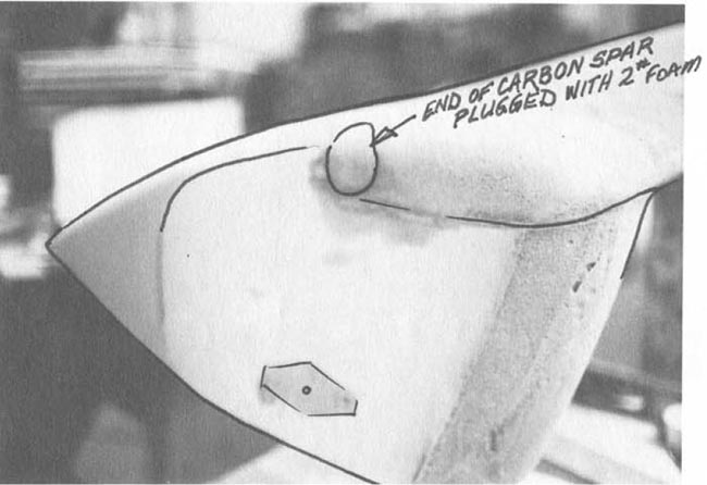
We didn't attempt to shape BL0-0 cores for a micro joint, but instead, left a gap to be filled with pour-in-place #2 density (x-40 available from Aircraft Spruce). Build a dam with cardboard and duct tape bottom gap. Sand fair after cure (usually about 30 minutes).
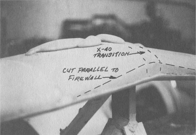
Fill Gap with X-40 - Sand L.E. Flush with Firewall
Note: Center blocks (BL15-'0-0') are shown with straight leading edge (BL100-BL0-0) BL15-BL0-' blocks should be parallel to firewall at leading edges, thus eliminating approximately .9" sweep BL0-0 - BL15. You can hand shape the inboard blocks since surface contour is not a critical flying surface.
Do a final check top and bottom of cores for transition errors, warpage, etc. Place additional support members (blocks 31.9 & 74.4) in appropriate positions to assist core support for glassing. . .
Hold Everything together with T-pins and Rubber Bands
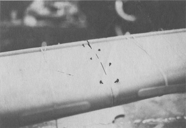
. . . We made random felt pen marks on cores ±45° to assist unidirectional cloth alignment.
Felt pen marks on cores ±45° to assist UNI alignment
Micro foam cores and allow an hour or 2 set up time before glassing.
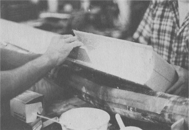
THE LAYUP:
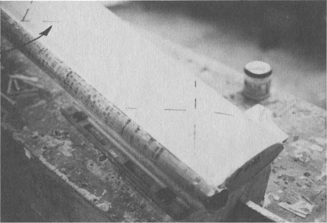
Better conservation of cloth can be employed by fitting scrap triangle with selvage edge inboard for first pull. (e.g.)
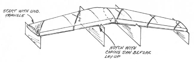
Scrap Triangle of UNI to Start
Allow UNI to wrap spar at T.E. and let cloth drape tangent at L.E.
Canard skin lamination schedule:
Bottom -
- 2 ply at 45° to the spars (90° to each other)
- 1 ply spanwise
- Overlap the spars with all 3 plies outboard of the caps and overlap the caps.
- Knife trim the skins at the leading edge. After curing, sand to taper the skins between 0 and 1 on the hotwire templates.
Top -
- 2 ply at 45° to the spars (90° to each other)
- 1 ply spanwise. We let selvage edge parallel L.E.
- 1 ply spanwise to BL15 each side for extra "heel" protection. Overlap the spars and the bottom skins on the spar by about 1 1/2". Overlap the caps. Overlap the leading edge of the bottom to about 1 1/2 on the hotwire templates.
- Knife trim leading edge, let cure 24 hrs.
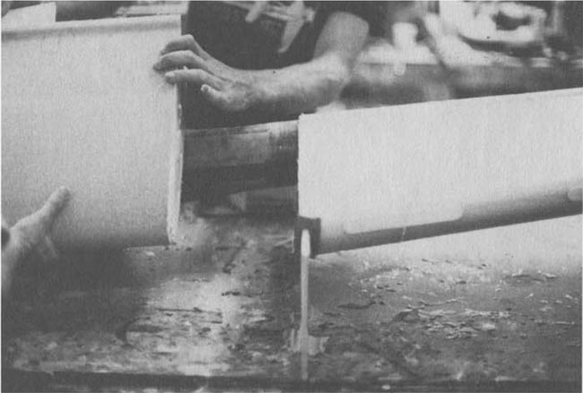
SLOT CORES:
Place the trailing edges of the slot core templates at the edge of the foam blocks and hotwire only the elevator slot areas. Next, glass these with 2 BID. NOTE: Put down some peel ply in the area shown before glassing. Let cure.
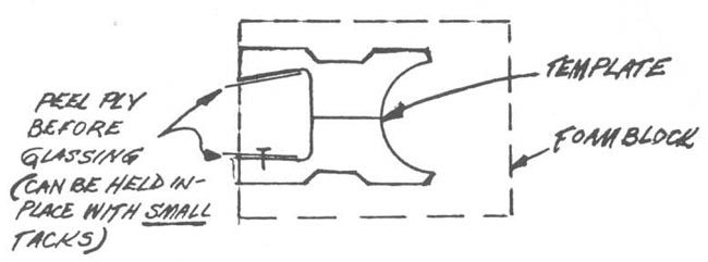
Hotwire and Peel-Ply the Elevator Slot Cores
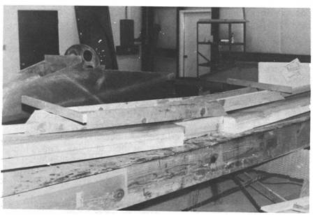
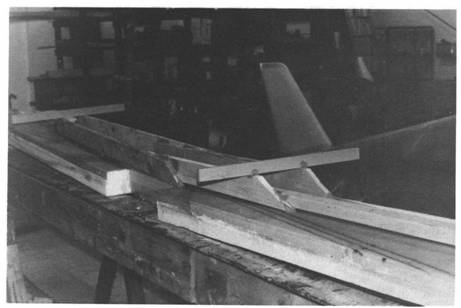
Use lumber as shown in the Q2 Plans before turning the canard over. Not as much will be required due to the stiffness of the spars.
EDITOR'S NOTE:
Although the LS1 Instructions invite you to "Use lumber as "shown" in the Q2 plans." The Canard chapter (Chapter 10) of the Q2 plans doesn't actually have any pictures of this.
Q-2 Plans: Page 10-4
Build a framework out of scrap lumber and bondo to hold the canard jigged in place while you turn it over. As shown in the pictures in the MAIN WING chapter in the "Laminating The Top Skin And Top Spar Caps" section, we suggest that the lumber run from tip to tip with a few cross pieces. Don't get fancy, just tie everything together so that the main wing won't move.
Next, when you are sure of your framework)break loose the canard core female jigging templates with a hammer (they won't be needed again), and turn the canard over so that the unglassed cores are upward. Set the canard on the jigging table once again.
Check the canard tip level lines. Jig, and shim, and bondo until the canard tip level lines are absolutely perfect; almost, or maybe, doesn't count. Then use bondo to secure all of the jigging so that a jackhammer will be required to remove the canard from the jigging table.
EDITOR'S NOTE:
The pictures with the lumber (on the canard) are actually in the Main Wing chapter (Chapter 9) of the Q2 plans as shown below. And I think the picture shows them building a Single Seat Quickie. How could anyone be confused by this?
Q-2 Plans: Page 9-4
Build a framework out of scrap lumber and bondo to hold the main wing jigged in place while you turn it over. As shown in the pictures, we suggest that lumber run from tip to tip with a few cross pieces. Don't get fancy, just tie everything together so that the main wing won't move, (and, yes, we know the pictures show the canard, but we forgot to take some of the main wing jigging).
Next, when you are sure of your framework, break loose the main wing core female jigging templates with a hammer ,(they won't be needed again), and turn the main wing over so that the unglassed cores are upward. Set the main wing on the jigging table once again.
Check the main wing tip level lines. Jig, and shim, and bondo until the main wing tip level lines are perfect; almost doesn't count. Then bondo the heck out of the jigging as if you were expecting a few kids to use your shop for playing cowboys and Indians.
After the canard has been covered, attach the slot cores with micro. Some sanding may be required to allow for the skin overlap on the spars. Both the slot cores and the elevators are exactly the same size and in the same position as in the Q2 Plans. . .
EDITOR'S NOTE:
The SIZE of the slot cores is (again) shown on page 5-2 of the Q2 plans.
The problem with that is that the Elevator Foam Slot Cores for the GU canard (shown in the Q2 Plans) are actually attached initially to the Leading Edge of the Canard Foam Core. With the LS1 Canard the Slot foam cores are separate templates. Just be sure to cut the Elevator Slot Foam Cores out of the same pieces of foam that you cut the Leading Edge Foam cores out of as reapeated below:
Q-2 Plans: Page 5-2
CANARD CORES
The outboard and inboard canard cores are cut from skewed, parallelogram style blocks, with the exception of the canard center section. The reason for this is to obtain the proper sweep of the canard when the cores are jigged together later.
Begin by squaring up the 10" x 20" X 96" nominal dimension block of polystyrene foam to obtain a length of 51.2", with the skew as indicated. Next, using the sketch provided, hot-wire the outboard canard foam cores. Note that the bottom set of templates are upside down, so as to obtain the proper geometry upon jigging.
Next, find the extra pieces from the 10" x 24" blocks (2) and face them up to the dimensions shown. These two blocks are used for the inboard elevator cores and inboard canard cores. The portions not used will be used later for the outboard elevator cores.
Don't forget the cutouts for the elevato0 torque tubes. After the elevator cores have been hot-wired, cut along one of the lines (e.g.4-A-B) and hot wire down that slot and around the inside (e.g. 4-A-B-C-D-E-F-G-H-I-B-A-4) and out again. Then cut along the other line (e.g. 4-F) and hot-wire along that slot to complete the cut.
EDITOR'S NOTE:
The POSITION of the GU slot cores is shown on page 10-6 of the Q2 plans.
However, the plans DO NOT discuss HOW or WHERE to install the brake lines and pitot tube on the LS1 canard. This is one of those areas that will require a discussion with a builder/flyer that has gone befoe you. Hopefully, this page will generate a few comments below, or a future article for the newsletter.
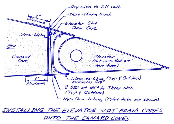
Q-2 Plans: Page 10-6
INSTALLING THE ELEVATOR SLOT FOAM CORES
This step is critical to having a nice looking canard and elevator union, so follow the directions carefully.
To start out with, the elevator slot foam cores that you hot-wired way back when were pur posely made longer than neces?ary. Your first task is to size them for the correct length. To do this, you must measure your fuselage width at the fuselage/elevator slot foam core junction. Take measurements of the canard, skip ahead to the sec tion on "Mounting The Canard To The Fuselage", and determine that dimension, on either side of BL00. Mark the proper points on the canard. Wait to trim the inboard elevator slot foam cores until after they have been installed on the canard.
Next, determine where to trim the outboard elevator slot foam cores. Since each elevator was made 72" long, measure 6 feet plus 1 inch (for elevator/fuselage clearance) from your first mark outboard and place another mark. This is where the outboard elevator slot foam core will be trimmed, but, as before, wait until after installation to do it.
The elevator slot foam cores are unique in that both the brake line conduit and the pitot tube must run through the lower, forward edge as shown on the sketch.
The pitot tube runs out the right canard, exits at about BL40, and is shaped as shown.
In the right canard, the brake line conduit enters the inboard end of the elevator slot foam core within 1/2" of the top edge, and continues all the way outboard to the end of the outboard elevator slot foam core on the right side of the aircraft. Let the Nylaflow tubing extend about 4" beyond the end of the slot foam core. On the left canard, do the same routing. You should use a router bit in the dremel to route out the foam. Any extra "room" in the foam is filled with dry micro. Both the brake line conduit and pitot tube are installed with 5-MIN dabs to hold them in place, and then surrounded with dry micro, as shown. Keep both lines, but particularly the brake line conduit, as straight as practical. The pitot tube tubing should extend into the fuselage about 12".
The elevator slot foam cores are installed to the canard shear web with micro-slurry on the foam cores and epoxy on the shear web (don't forget to remove the Peel Ply!), plus a few dabs of 5-MIN to keep the two _ttached during cure.
It is easier to check clearances top and bottom if the canard is jigged vertically on the jig table. This will also keep the joint from running. By this time, you should be so good at jigging, that we won't even talk about how to do it.
The important point to remember is that at the shear web attach point along the span, the top and bottom of the elevator slot foam cores should flow smoothly into the top and bottom surfaces of the canard, respectively. If the elevator slot foam cores want to stick up a little bit, this is OK since that can be sanded later. Any dip, however, will have to be filled with micro. When you have done your best to carefully fit the shear web joint top and bottom then mix up the micro-slurry and epoxy and join the elevator slot foam cores to the canard.
Once the attachment has cured, then the fun can begin. Trim the elevator slot foam cores back to the "Eventual Trim Line". Next, sand down the "tails" so that you can achieve a minimum of 0.4" of glass-to-glass bond with the inside lamination, while at the same time fairing everything nicely into the canard contour forward of the shear web. At the glass-to-glass bond area, you must sand away all micro and epoxy and get down to the glass. Spend some time looking at the surfaces getting the best alignment that you can. When everything is ready, laminate 2 BID at 45 degrees to the canard shear web on the elevator slot foam cores, being sure to achieve at least 0.4" of glass-to glass bond, and lapping up onto the canard at 1 east 1". Note that the sketch ca 11 s out dry-mi cro fill if required at the top and bottom of the shear web joint. Trim the inboard and outboard elevator slot foam cores at the marks previously made on the canard.
Your canard should now be looking more like a canard, and less like a lump of foam and glass.
. . . After the micro has cured, sand the tabs on the cores down to the canard surface and glass with 2 BID.
EDITOR'S NOTE:
Be careful - Now that you have the Elevator Slot Foam Cores installed - you will be told that it would have been better if you had waited to build the elevators first. Maybe building the elevators should go at the start of the instructions instead of the end?
Note: It may be easier for you to build the elevators before installing the slot cores & trial fit the attach structure. The slot cores can be treated as fairing, sectioned, & installed around CS 15, 17, & 19 with one ply BID. Be sure to micro high density white foam blocks in place as hard parts detailed in Q2 Plans.
Next, build the elevators. Hotwire cores are the same as is shown in the Q2 Plans. Note that there is only 1 slot for cutting the hole for the torque tube. When bonding the torque tubes in the elevator cores, use a brush and micro down this slot.
Use the templates provided for jigging the elevators for glassing. It is probably best to jig them after the torque tubes are installed, but before the micro has cured. Apply peel ply to bare foam trailing edge 1/4" to 3/8" before glassing for a stippled close-out. Glass with 2 UNI at ±45°. When you sand down the tabs for glassing the top surfaces, note that the elevator has a blunt trailing edge. Refer to the hotwire templates. After glassing, sand the elevator trailing edges to length. Then remove some foam (1/4") and fill with dry micro to prevent the skins from peeling. Coat with pure epoxy first.
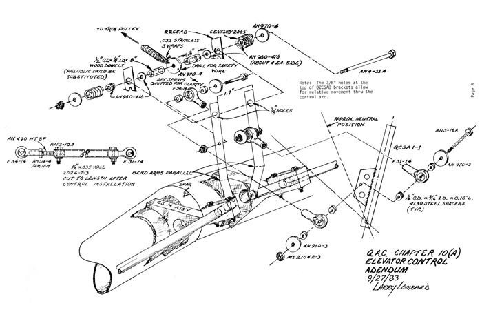
Refer to the Q2 Plans for installation of the elevators, QCSM2's, CS17, CS14, CS15, etc.
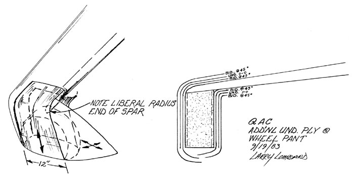
Build the wheel pants using the templates provided. Refer to the Q2 Plans for detailed instructions. Note that these pants are designed to fit the standard tires only. We will design pants for the 500x5 tires later. You may modify the design yourself by referring to the Q2 Plans.
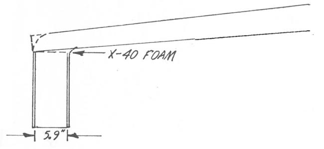
To fit pants to wing, you may want to fill taper with X-40 foam.
EDITOR'S NOTE:
The following recommendation about "toe out" was superceded in 1997 by the David Gall Wheel Alignment. It is strongly suggested that you perform the wheel alignment . . . and perhaps even wait to attach the wheel pants entirely . . . after you are able to place a working load on the canard. Under load (on the ground) the canard will bend and the wheels will splay out throwing off your careful "bench measurements."
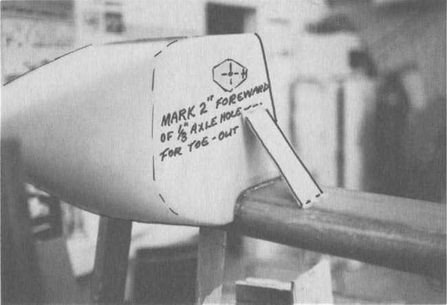
Install the wheel pants in the same manner as is detailed in the Q2 Plans. Note extra UNI plys. We recommend establishing about 1/2 to 3/4° toe out. This is accomplished by placing a mark on the inside face of each pant that is 2" forward of the axle hole centers, then sighting on the marks for alignment. This seems to improve ground handling.
SPARROW STRAINERS:
These are trim devices required due to the pressure distribution of the LS(1) 0417 Mod Airfoil. Through testing, we have found the most effective position to be inboard (both sides of course).
Construct as follows:
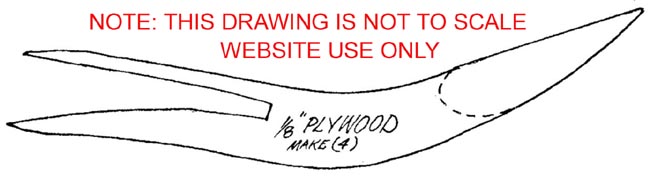
Make 4: 1/8" plywood stringers.

Also Make 2: 11.5" balsa wing sections.
5 minute epoxy 2 plywood stringers and airfoil section on elevator about 1" outboard from inboard but line. (duct tape and large rubber bands are helpful here). Make small micro radius at stringer attach to elevator. Cover everywhere with 1 ply BID. (We used a lighter weight tooling cloth available at most hobby houses - about 4 oz.) This cloth is also a good choice for antenna close-outs.
Installing the new canard to the fuselage will tax your imagination. Not unlike Chapter 12-2 of the Construction Plans, it may take several hours to trim and jig the canard to the fuselage and in reference to the wing. You should exercise extreme caution in leveling the fuselage in all quadrants and jigging the canard . (You did bond reference levels to canard while it was jigged for glassing, didn't you?)
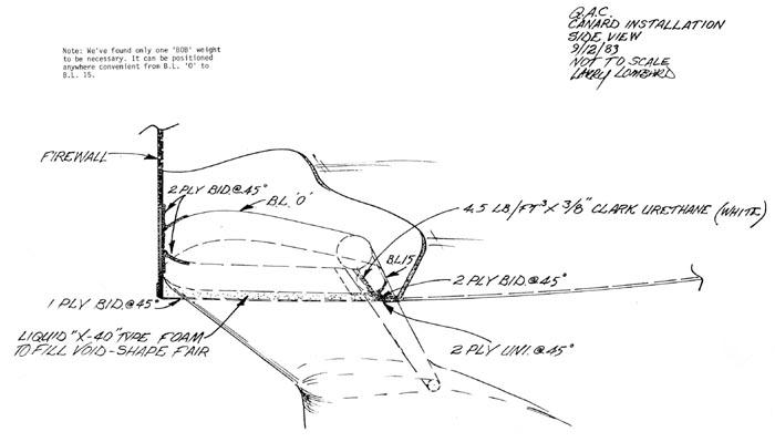
Please note: Your LS-1 mod canard mounts at zero incidence as opposed to the G.U. Also, without a straight center section as on the G.U., there is no bottom reference to the fuselage. Therefore, it would be best to have the magneto box cut-out completed as a reference to the apex of the LS-1 for final canard- to-fuselage assembly.
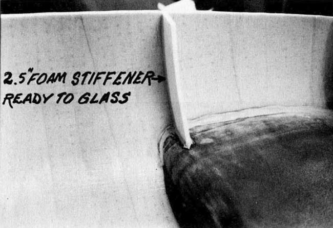
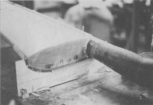
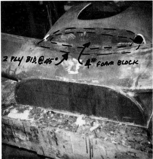
After canard is installed with liberal dry micro radius and 2 ply BID, micro transition blocks from fuselage bottom to canard (4# x 3/8" white urethane) and 2 ply BID inside and outside lapping at least 1" everywhere. (See drawings and photo.)
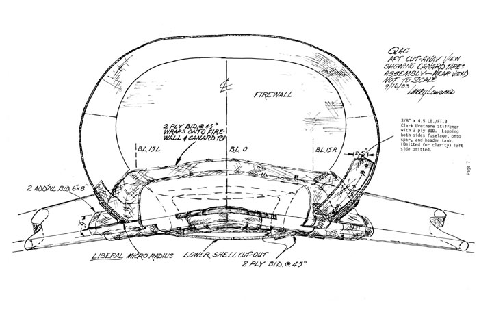
Then, with 2# urethane block or, better still, X-40 pour-in-place, fair bottom of fuselage cut-out to firewall and closeout with 1 ply BID @ 45°.
Next, install additional 2.5" stiffeners left and right sides of fuselage centered over spars as per drawing.