Q-talk 117 - May/June 2006 - index


- Details
- Category: Q-Talk Index
- Published: Wednesday, 23 December 2009 16:24
- Written by Doug Humble
- Hits: 2614
 | Quickie Builders Association Together we build better planes! May/June 2006 Issue Number 117 |
One Down, One to the Right,Hanging an 0-200 on the firewall
by Jerry Marstall
That's the mystical offset for the 0-200 engine on the Q-200. One degree down and one degree to the right; sounds easy enough. I am sure that over the years Q-talk published several articles on techniques for attaining this exact positioning, but being a Revmaster rider at the time, I didn't pay them due attention. Nor am I disciplined enough to ponder through all the back issues.
Now in the throws of an O-200 conversion, all at once I have a need. Knowing that the Q doesn't have a flat surface or square face anywhere, I wasn't assured that I had mounted the firewall perfectly vertical and square with the fuselage. So how was I going to know when I had attained the mystical one down and one to the right? I am sure that the engineers and mathematicians among you have the snazzy formulas to easily do this. Being a business major, I had to come up with a simplistic means to establish this critical offset. The method I devised should align the engine properly regardless of any built-in misalignment of the firewall and/or tail section. If it doesn't, I am relying on the engineers among you to correct me.
First, here are the tools I used.
1. Nylon fishing line 7 Ft.
2. Large paper clip
3. Masking tape (technical stuff, huh!)
4. Two laser levels. At least one of them must project a line; the other may be a dot.
5. A tripod for the line projecting laser level
6. Two plum bobs with suspending strings
7. A 4 foot vertical pole with a stand
8. Spacing washers: 1/16" and 1/8" thickness
SETUP:
STEP ONE: Mount the engine with the prop extender, but without any spacers and torque to specs. Also mount the tail section.
STEP TWO: Level the plane along both the longitudinal and lateral axes. If you didn't mount a bubble level somewhere on the fuselage during initial construction, make sure you affix reference levels this time because during this process you will be checking and rechecking that the aircraft is level.
STEP THREE: On each of two pieces of masking tape mark 5 parallel vertical lines, %" in length, 1/10" apart and number the lines 0, 1, 2, 3 and 4.
ZERO DOWN:
First, you need to find the level position, or "zero down", of the engine as it relates to the firewall.
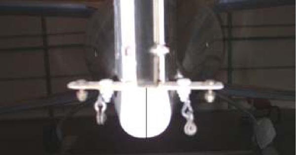
STEP ONE: Locate and mark the center of the prop hub. This can be done by first covering the entire face of the prop extender with masking tape. With a straightedge, draw lines between the centers of opposing lugs on the prop extender. This will result in three crossing lines. The center of these crossing lines is the center of the crankshaft.
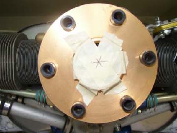
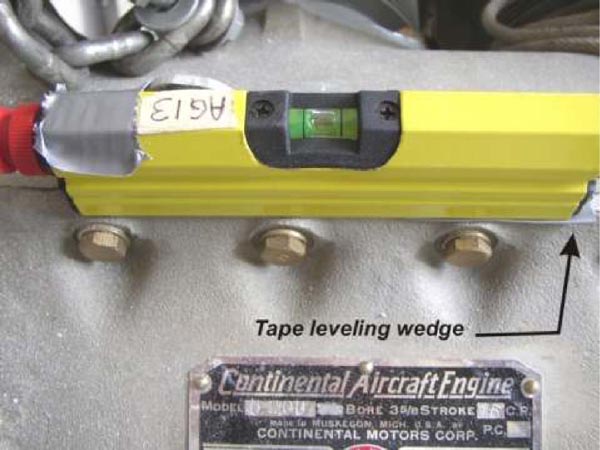
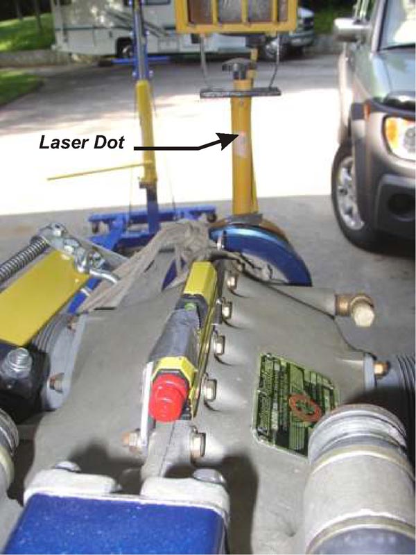
STEP TWO: Locate the flat spot on the top of the crankcase split line. Place the dot projecting laser level at this location and mark exactly where the laser level is located so you can put it back in the same position if you remove it while removing the engine later on. Temporarily tape the level to the top of the crankcase with the laser pointing forward. If necessary, level the laser level with a removable shim.
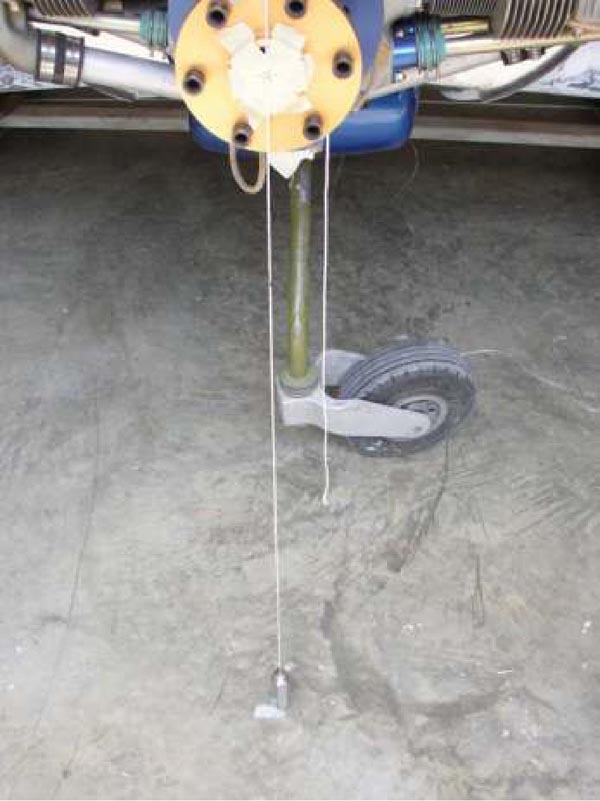
STEP THREE: Place the vertical pole directly in front of and snugly against the prop extender. Turn on the laser level and position the vertical pole to where the laser projects the dot onto it. (Note: you may have to darken your shop in order to see the projected dot.) Then place one of the pieces of tape vertically on the pole with the "0" line at the top and directly under the dot (see photo below).
You have just located the engine zero degree down position. If you didn't have to use a shim to level the laser level, the crankshaft (engine) is vertically aligned along the longitudinal axis and is "zero down". If you did use a shim, your engine is already offset, you just don't know how much yet.
ZERO TO THE RIGHT:
Now you need to determine the lateral, center position of the engine as it relates to the entire length of the aircraft; the "Zero Right" position.
STEP ONE: Tie the ends of the fishing line to each of the bottom motor mounts. Let it loop down to within 12" the floor. Push the line as far back on the mounts as possible and tape them there. You don't want them sliding forward during the process. (Note: Don't let the tape interfere with the natural drop of the line). Hook the paperclip to the line and allow it to slide to the low point of the line.
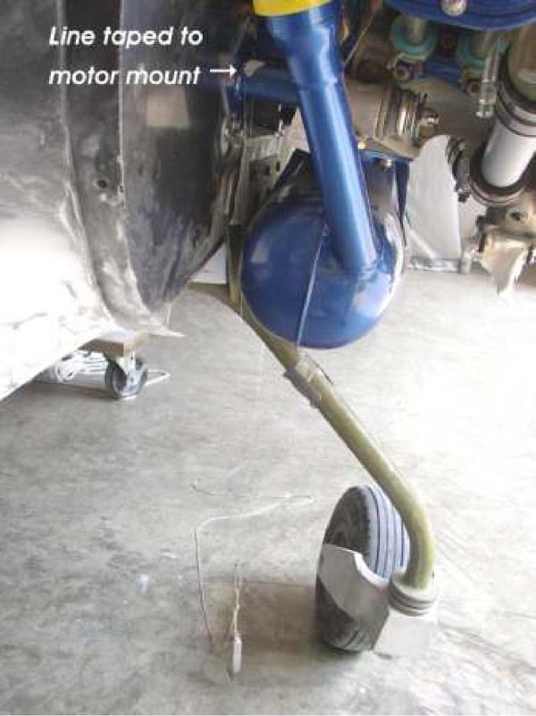
Take the string of one of the plum bobs and run it
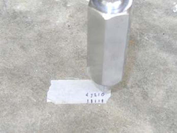
through the bottom loop of the paperclip. Tie it off so that the bottom of the bob is about %" above the floor. The plum bob's weight centers it at the bottom of the fishing line loop thereby locating the exact center between the motor mounts.
STEP TWO: Suspend a plum bob from the face of the prop extender. Place the string attached to the plum bob over the face of the prop extender centerline and lower it to with %" of the floor. Tape it in place.
STEP THREE: Draw a dark, narrow, vertical line below the rudder, dead center on the tail-end of the fuselage.
STEP FOUR: Set the straight line projecting laser level on the tripod at the tail of the plane. Level the laser level and position it so that the line is projected vertically. Position the vertical laser line so that it aligns with the vertical line on the tail and the plum bob hanging from the paper clip. Instead of trying to align the laser line on the center of the plum bob, align it on the string that suspends the plum bob. The laser line easily illuminates the string. Its tricky but with a little patience you will get them to align.
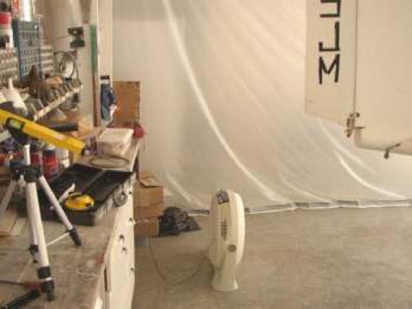
You will see that the laser actually projects its line on the floor for the entire length of the plane. The line on the floor will project past the plum bob hanging from the prop extender. Place the second piece of tape on the floor beside the plum bob hanging from the prop extender. The "0" directly on the laser line, with the scale extending to the right-side of the airplane. The tape scale lines should be under the plum-bob hanging from the prop extender.
You have just located the engine zero degree to the right position.
If the plum bob on the prop extender is hanging directly over the laser line on the floor, the crankshaft (engine) is horizontally aligned along the longitudinal axis and is "zero to the right". If the plum bob is hanging either side of the laser line then you have a built in offset. The amount is indicated by the numbered tape scale on the floor.
One of those mathematical geniuses I previously mentioned determined that if the center of the engine crankshaft is angled %" from center, measured at the front of the prop extender, this would equal a one degree bias. So all we have to do is determine the size of the spacers required to cock the engine down %" and to the right %" which is between the 2 and 3 marks on the masking tape. So, how do we do this?
Choosing the correct number of spacers for each motor mount is a reiterative process. I chose to attack the "one degree down" requirement first. All I had to do was slip spacers on each of the top mounts until it was positioned properly.
Instead of removing the engine each time to trial fit spacers, cut slots in the spacers. This allows you to easily slip trial spacers on and off of the loosened engine mount bolts. An engine hoist is very helpful in holding the engine while loosening the motor mount bolts for trial fittings.
Bevel four of the 1/8" spacers to form a wedge on the face of the spacer. (The exact number needed can't be determined until you actually start fitting) These can be used to assist in angling the engine by rotating them in the desired direction.
Begin by installing the beveled spacer. If you find that you need more offset, place a straight spacer behind the beveled spacer (closest to the engine mount). This method increases the offset while maintaining the relatively straight bore that the motor mount bolt requires. If you need a third spacer, sandwich the beveled one in between the flat washers.
ONE DOWN:
Steps.
1. Check aircraft is level
2. Check engine block laser level is shimmed level
3. Turn on laser level and check dot at "0" on vertical pole. (adjust tape as necessary to position "0" under the dot)
4. Remove shim and allow the level to set on the top of the engine block. Note where the laser dot projects onto the tape scale.
5. Insert spacers as required to make laser dot project between lines 2 and 3
6. Torque motor mount bolts after adjusting spacers
7. Return to 1.
ONE TO THE RIGHT:
Steps
8. Align laser at tail of airplane to project on the vertical mark on rear of fuselage and on the string of the plum-bob hanging from the motor mounts.
9. Note where line is projected related to the tape on the floor. (adjust tape as necessary to position "0" on the laser line)
10. Insert spacers as required to make laser line project between lines 2 & 3
11. Torque motor mount bolts after adjusting spacers
12. Return to 1. (NOTE: Each time you change the "right" offset you need to reconfirm the "down" offset)
Once you discover the magical combination of spacers required to arrive at One Down, One to the Right, you can substitute solid spacers for the slotted ones.
You will want to devise a scheme for insuring that you get the spacers on the proper motor mount and in the proper order every time you remove and reinstall the engine. I chose to etch the motor mount location and the order of installation on each spacer. (RT [right top] 1 of 3, RT 2 of 3, etc).
If you choose to use beveled spacers, be sure to file alignment marks on the spacer and the motor mount so you can align the beveled spacer in the proper direction during reinstallation.
That's it. Nothing to it but to do it!!!
Articles from this issue:
Where was Sam hiding? - by Doug Humble
QBA on the grow! - by Doug Humble
Tri-Q Tail Skid - by Ron Weiss
The Little Engine that Could; Revmaster - Still an excellent power plant for the Q2. - by Rene Robertson
Service Bulletins - by Doug Humble
Fuel "O" ring issues - by Doug Humble
Enhanced On-line Tools - by Doug Humble
A current QBA member may have one free ad per issue. It may be a maximum of five lines of type and will be edited to fit space available. Items advertised must be owned by the QBA member. The ad contact must be a member name. Ads will be run for two issues and then the ad must be resubmitted. [EDITOR'S NOTE: Please note that these ads may no longer be valid. They are included here only as part of the online archive.]
For Sale: Lopresti Style cowls for Q200's and very streamlined wheel pants for Tri-Q's. Contact Earnest Martin at This email address is being protected from spambots. You need JavaScript enabled to view it. or phone 828-230-5378 Photos may be seen at the QBA web site in Issue 111
For Sale: Dynamic Propellor Balancing for Experimental Aircraft Contact Jon Finley at 952-423-6391 or This email address is being protected from spambots. You need JavaScript enabled to view it. www.finleyweb.net/balance
For Sale: Q2 kit never started. No engine & no LS1 canard. Kevin Evans 952-322-1054
For Sale: My father passed away recently and I am helping my mother to sell his Q2. It has a RevMaster engine and the Hobbs meter shows 95 hours, but we are not sure it has ever flown. The original builder was Bill Brei of Western PA. I have photo's that I can email you. Located at the New Castle, PA airport in Western PA. Bob Hazen (570) 398-8365 or email me at This email address is being protected from spambots. You need JavaScript enabled to view it.. PRICE REDUCED to $5500.00.
For Sale: Recently completed and great flying Q2 with 50 hours. 75 hp RevMaster engine. 160 mph cruise on 3.5 gph. $18,000 OBO. Located in Stockton CA at KSCK. Call Floyd Welch at 209-329-8145
For Sale: Q-200 project. Major components complete. Subaru EA81 engine available. Some instruments. All plans and most old newsletters. Eric Beeson 720-201-7992 Longmont, CO or This email address is being protected from spambots. You need JavaScript enabled to view it.
 |
| Just add wings! |
You can order a printed copy of Q-talk #117 by using the Q-talk Back Issue Order Page.