Q2 Plans Chapter 14 Page 14-05


- Details
- Category: Q-2/Q-200 Plans
- Published: Wednesday, 17 May 2006 15:05
- Written by Quickie Aircraft Corporation
- Hits: 2772
|
..... In order to provide a leakproof seal around the main fuel tank after installation, small stiffeners are placed along the fuselage sides so that, when installed, the main fuel tank will set down on these stiffeners, thus assuring good squeeze out of the flox and a good seal. These stiffeners are nominally of 1/411 square cross section, and made from the thin sheets of white foam. They are positioned by dry fitting the fuel tank in place, tracing around the main fuel tank on the fuselage side, and then lowering the traced lines the thickness of the main fuel tank after removing the tank. The stiffeners are installed with flox, and allowed to cure completely prior to mounting the main fuel tank permanently. Do not be concerned at the number of seperate stiffeners required to cover the tank perimeter. .....To install the main fuel tank permanently, it will first be necessary to notch the forward lower edge of the main fuel tank at BLOO so that the fuel line tubing will exit the tank there. Next, mix up both pure epoxy and flox. Paint pure epoxy liberally on all exposed areas of the stiffeners, to prevent contamination of the fuel later. Trough flox liberally on the top of the stiffeners, as well as on the fuselage bottom where the forward and aft edges of the main fuel tank will rest upon assembly. Next, trough flox around the edges of the main fuel tank that will come into contact with either the stiffeners or the fuselage. .....Insert the tank in place, and verify that you have good squeeze out of the flox everywhere to assure a good seal. Wipe off the excess flox on the top side as you make a flox radius between the tank and the fuse¬ lage. Laminate 2 BID tapes with a 111 minimum overlap to join the man fuel tank to the fuselage. Liberally apply flox around the exit of the fuel line to prevent leaks.  SEATBELT ATTACHMENTS
..... A very important safety feature of your Q2 is the individual seatbelt/shoulder harness assembly provided for each occupant. Previously, you have mounted the attachments for the shoulder harness in the main w_ng. In this section, you will install the mounts for the seatbelts, and, finally, install the seatbelts in your aircraft. Do all of the procedures exactly like these plans state; this section is your first line of defense in the event of a mishap. .....The seatbelt mounts are installed in the fuselage between the aft edge of the fuel tank and the forward edge of the seatback bulkhead. There is one outboard seatbelt attachment on each side of the cockpit, and a double seatbelt attachment of BLOO. .....The outboard seatbelt attachment is straight¬forward and ill ustrated herein. A piece of 1/4" plywood about 2.2" x 1.2" is sanded to fit the fuselage contour and beveled for the lamination of 7 BID over it; between the plywood and the fuselage skin use epoxy. The 0.7" MIN,overlap onto the fuselage is very important, as is making sure that the glass does not turn any sharp corners. The two holes for the AN525-416R14 screws may be drilled from the inside of the fuselage all the way through to the outside; the holes for the screws can be filled with dry micro later. The aluminum angle should be about 1.2511 in length, and permit at least 3/811 from the center of each hole to the outside edge. The angle should be installed permanently, and then the hole for the AN4-5A bolt holding the seatbelt itself drilled afterwards, so that the hardware does not interfere. Note that the seatbelt pulls off at about a 45 degree angle. You may wish to sit in the aircraft and pick the optimum FS for the seatbelt fittings prior to bonqing the plywood in place. The other side is a mirror image of the one illustrated. 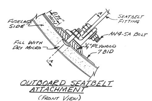 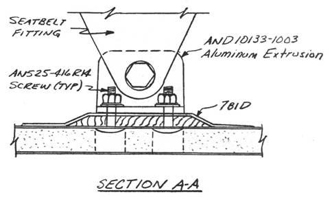 |
||||
CONTINUED ON NEXT PAGE |
||||
PAGE
14-5 |
||||