Q-talk 154 - Q2 Dual Engine Controls


- Details
- Category: Q-Talk Articles
- Published: Wednesday, 29 August 2012 16:01
- Written by Harold Dirks
- Hits: 5129
Dual Engine Controls
Written by Harold Dirks
Quickie 2 - N32DK
[EDITOR'S NOTE: In the last newsletter, we featured a beautiful Q2 co-owned by Charles Kuhlman and Harold Dirks. Harold gives us all a bit more detail about this unique Q-bird in the well documented article below. Their dual engine control set-up deserves the envy of all builders. Great job, and great article! Thanks Harold!]
Our Q2 has dual throttles and mixture controls. We built this capability into the plane when we originally constructed it in the late1980s and early 1990s. The pictures below, taken at that time with a 35 mm film camera, show the left, right, and center of the cockpit. The camera wasn’t one of the best, and the pictures have deteriorated over the last 20-plus years, so I apologize for their reduced quality.
 |
|
Left Side of Cockpit
|
 |
|
Right Side of Cockpit
|
 |
|
Center Cockpit
|
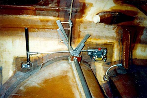
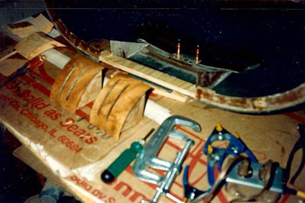
This article is intended as brief discussion of what we did to construct and install the dual controls for the engine. We started, as shown in the pictures, with two long 6061 aluminum tubes, nested one inside of the other, to connect the left and right throttle and mixture controls. The outer tube connects the two mixture control levers and the inner tube connects the two throttle levers. The levers began with four disks cut out of 1/8-inch-thick 6061 aluminum plate. The disks were not perfectly round; the outsides were shaped to provide places to attach the aluminum bar-stock levers with rivets. The disks were drilled to fit the outside diameter of their respective tubes. The disks were then soldered to the ends of the tubes with a propane torch and those special aluminum-soldering rods. There was some apprehension about using this method, but the soldered joints have held up fine for over 20 years of use.
The throttle control on the left side of the cockpit is v-shaped, with the short lever connecting to the throttle cable and the long lever used as the pilot’s throttle control. The left-side mixture control is arranged the same way. The right side controls just use long levers.
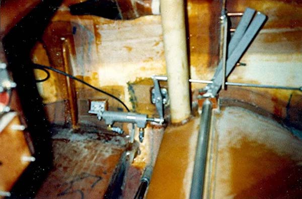
The ends of the two tubes rest in ½-inch-wide phenolic bearing blocks, which are fastened to the top of the seat gas tank. The four bearing blocks each started out as a rectangular block which is first drilled at each end of the long dimension to receive the clamping/mounting bolts. Next, the blocks are sawed in half the long way to yield top and bottom pieces. Next, the top and bottom pieces are bolted together and a hole sized to receive the tube is drilled at the center of the block. When finished, each half-block has a half-circle hole in the middle and a vertical bolt hole at each end.
The bearing blocks mount to a rectangular piece of 3/8-inch-thick plywood that has four bolt holes drilled in it to match the bolt holes in the bearing blocks and to provide the proper lateral spacing of the blocks on the tubes. The bearing blocks are mounted to the plywood by inserting the bolts at the bottom of the plywood and up through the blocks. The nuts go on top of the blocks. We partially-drilled the plywood bottom at the four bolt holes with a larger bit size that allows countersinking the bolt heads even with the bottom. The empty spaces around the bolt hex heads are eventually filled with an epoxy/flox mixture before the plywood mounting pieces are permanently floxed to the seat tank. It was important to ensure that the entire dual control system operates perfectly and is positioned correctly in respect to other units in the cockpit before it was permanently installed.
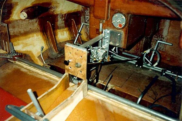
The picture of the center of the cockpit shows a wooden strip installed under the aluminum tubes. This strip is used to mount a long U-shaped fiberglass tube (not shown) that covers the aluminum tubes to allow them to turn freely without interference from the seat cushions and the legs of the pilot and passenger. The fiberglass tube was made using a PVC pipe for a mold.
The next old picture shows the parts that were eventually mounted at the junction of the top front of the arm rests and the vertical sides of the instrument panel. These parts were made of thin plywood and covered with the same type of Formica sheet that covers the entire instrument panel.
 |
|
Throttle Quadrant Covers
|
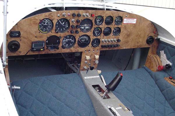
The next picture was taken when the airplane was nearly completed and it shows how the throttle and mixture controls look in the cockpit. The levers behind the controls are brake levers. Either lever operates the brakes on both wheels The left-side brake lever operates the master cylinder and the right-side lever operates the slave cylinder. The two white push-pull controls at the top of the center console operate independent parking brakes for each wheel. This system allowed the plane to turn around the stopped wheel when necessary during parking, but was really installed to accommodate a future change to the independent brakes we now have.
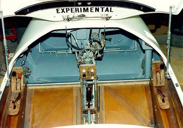
The last picture shows what the right side engine controls look like today in the finished airplane. The left side controls look the same, but are unfortunately out of the picture.